
High speed ramp generator

a generator and high-speed technology, applied in the field of electronic devices, can solve the problems of inability to fully digitally communicate time delay incident, and inability of prior art systems to achieve full-duplex digital communication across a single transformer, and achieve the effect of accurate separation

Active Publication Date: 2008-04-01
MAXIM INTEGRATED PROD INC
View PDF6 Cites 10 Cited by
  • Summary
  • Abstract
  • Description
  • Claims
  • Application Information

AI Technical Summary

Benefits of technology

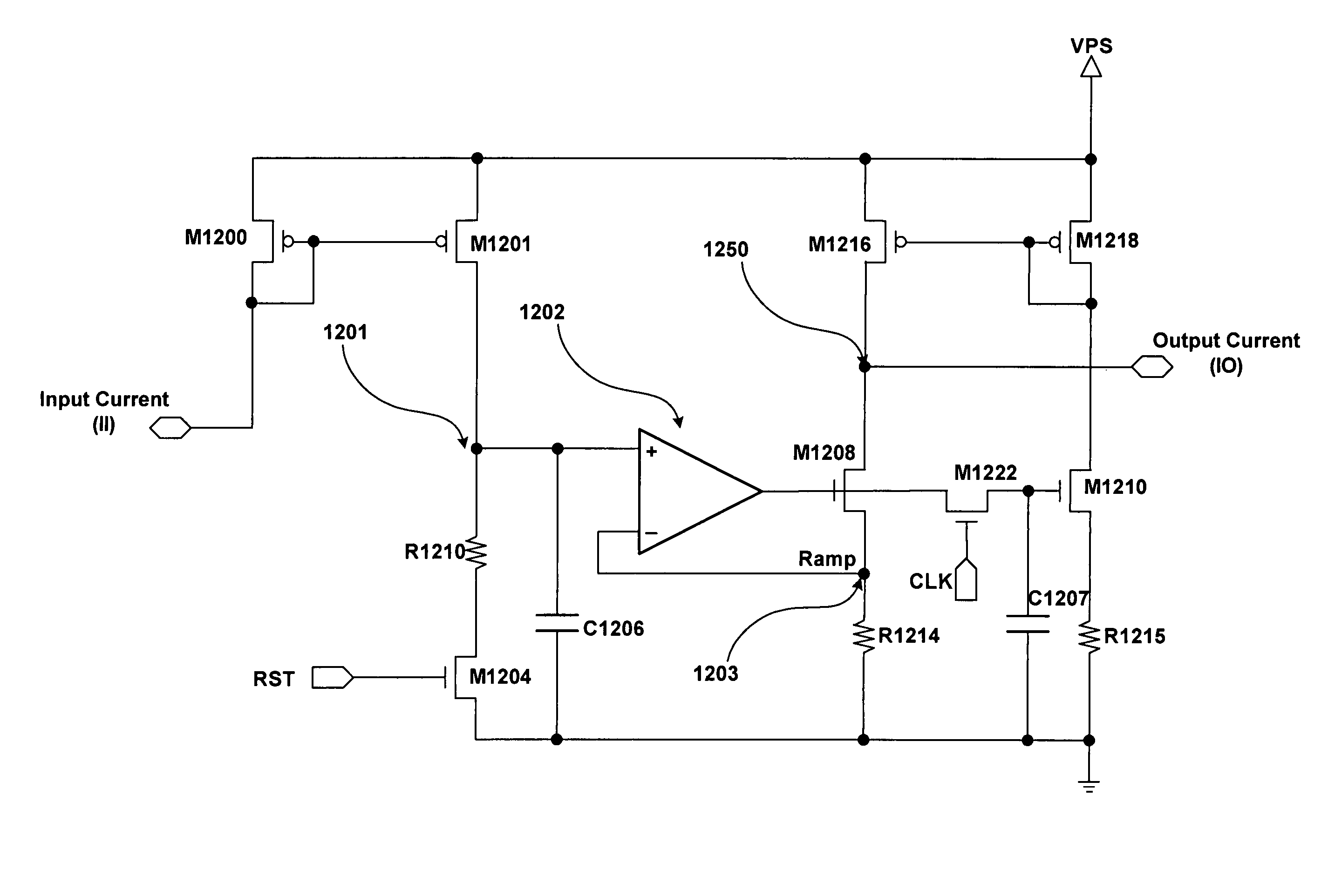
The invention provides a high speed ramp generator apparatus that improves ramp response without the delays of a simple integrator approach. It uses a closed loop system with operational amplifiers, capacitors, and resistors to generate a high speed ramp current output. The second ramp current is generated by current-mirroring the first ramp current and is subtracted from the first ramp current output, yielding substantially zero net output current. The second ramp current is then turned off to freeze it, resulting in an immediate current ramp output that is not dependent on other components like prior art feedback circuits. The invention also provides a method and apparatus for bi-directional communication across a transformer by driving a first communication signal in one direction and modulating the load impedance on the line side in the opposite direction. The invention allows for accurate separation of the load current from the magnetizing inductance current at higher data rates than would be possible with ramp generators of the prior art.

Problems solved by technology

Because the ramp generator is an integrator with feedback, there is a time delay incident with the starting and stopping of the integrator.
This time delay may not be desirable in some applications.
Prior art systems are incapable of full-duplex digital communication across a single transformer.
However, the use of multiple transformers to achieve two-way communication is expensive in terms of cost and space.
Unfortunately, the electrical characteristics of a transformer make it difficult to simultaneously drive a transmit signal onto, and detect a receive signal from, the same port of a transformer.
Any delays in the performance of the ramp generator (e.g., onset or shut-off delays) can cause timing offsets in the corrective current signal, degrading the accurate cancellation of the magnetizing current and increasingly impacting receive data detection performance as the communication data rate rises.

Method used


Image

  • High speed ramp generator
  • High speed ramp generator
  • High speed ramp generator

Examples


implementation example

DAA Embodiment

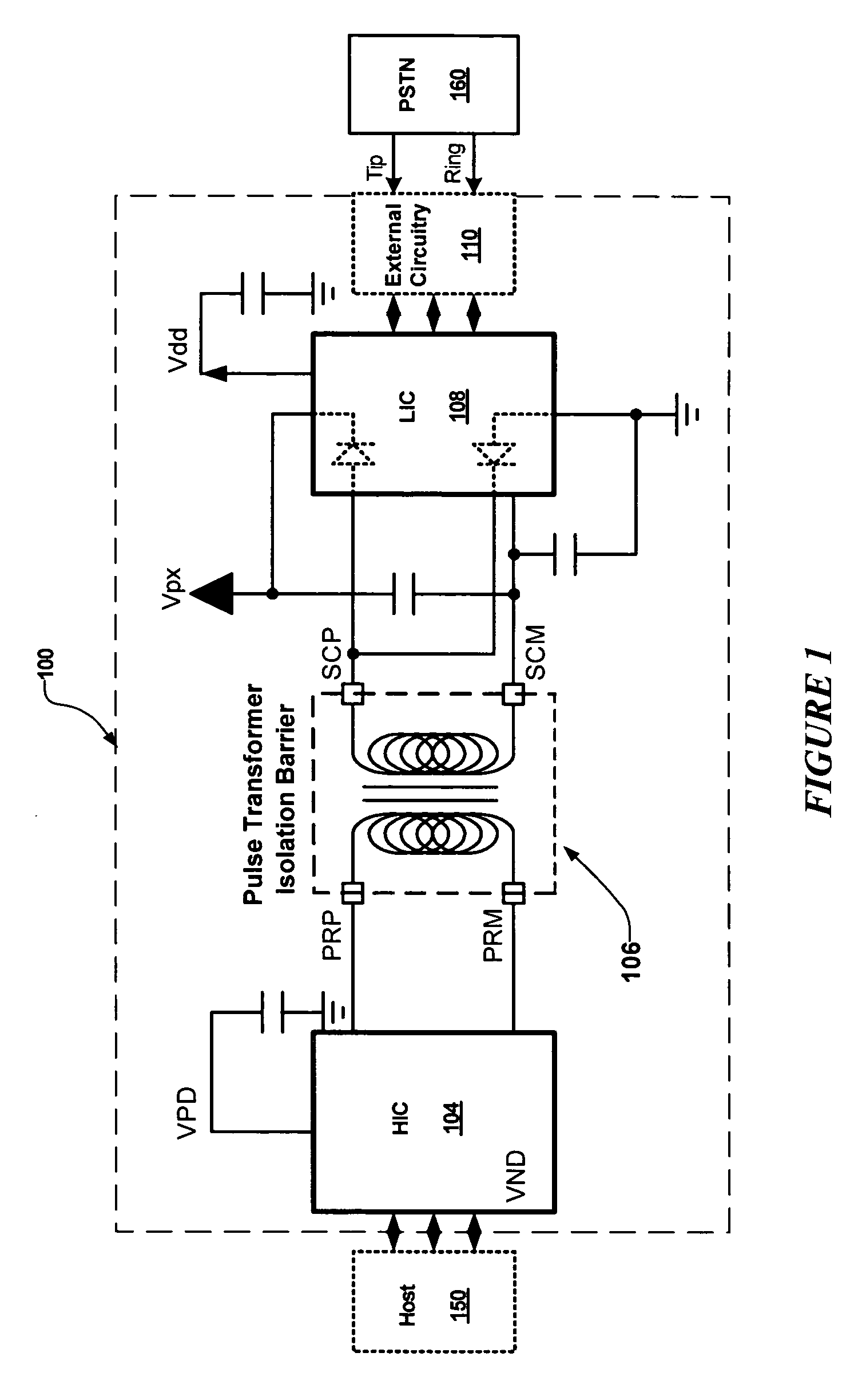
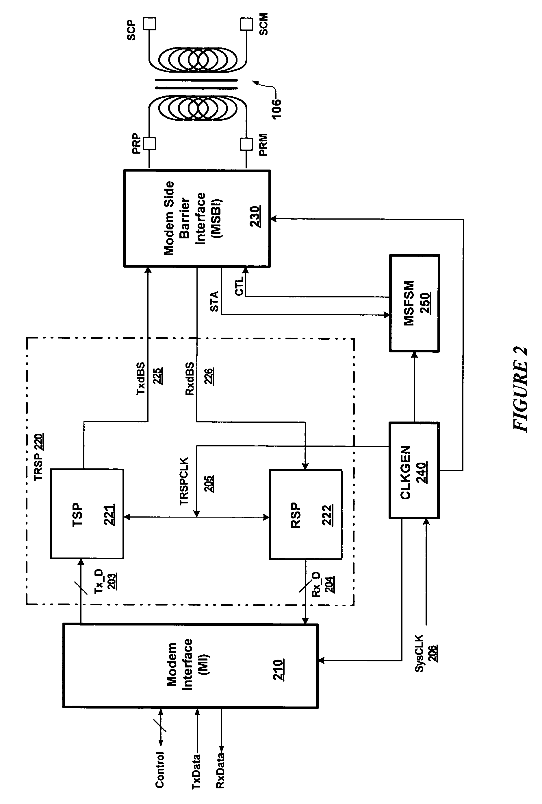
[0043]Embodiments of the present invention may be used in communication circuits to support simultaneous, bi-directional communication across a transformer, for example, in connection with an isolation barrier of a DAA circuit. Thus, for purposes of illustration, the method and apparatus of the present invention will be described below within the context of a DAA isolation barrier implementation. Although the discussions herein are concentrated on the disclosed DAA environment, it should be apparent to those of skill in the art that the principles expounded herein are applicable to any application wherein it is desired to precisely control a ramp current, e.g., to cancel or balance the magnetizing inductance current of a transformer, or other inductive circuit or circuit component.

[0044]Signal communication across an isolation barrier is generally useful for telephony, medical, industrial, and other applications wherein it is desired to separate voltage potentials. In ...


PUM


Abstract

A high speed ramp generator is presented. The high speed ramp generator is advantageous over the prior art because it provides a ramp response without the delay incident with a simple integrator approach. A closed loop system generates a continuous ramp and, in an open loop manner, subtracts a mirror of the current ramp from itself. A switch is provided which when open, triggers an immediate current ramp output that is not dependent on the amplifier or any other component of prior art feedback circuits. Two such ramp generators may be used in tandem to provide alternating portions of a precision ramp signal, such as may be used to cancel the magnetization current induced in the primary of an isolation transformer.

Description

CROSS-REFERENCE TO RELATED APPLICATIONS[0001]This application claims the benefit of priority from U.S. Provisional Patent Application No. 60 / 695,241, entitled “High Speed Ramp Generator,” filed on Jun. 28, 2005, the specification of which is herein incorporated by reference in its entirety.BACKGROUND[0002]1. Field of the Invention[0003]This invention relates to the field of electronics. More specifically the invention relates to a high speed ramp generator.[0004]2. Background Art[0005]In the prior art, ramp generators are generally closed loop integrator circuits. Because the ramp generator is an integrator with feedback, there is a time delay incident with the starting and stopping of the integrator. This time delay may not be desirable in some applications. One example of such an application is high speed data communication across an isolation barrier, as described herein.[0006]An isolation barrier is generally used in applications in which it is desired to keep voltage potentials...

Claims


Application Information

Patent Timeline
Patent Type & Authority Patents(United States)
IPC IPC(8): H03K4/06
CPCH03K4/48
Inventor HERSHBARGER, RUSSELL
Owner MAXIM INTEGRATED PROD INC
Learn More