Small-size direct-acting actuator

a direct-acting actuator, small-size technology, applied in the direction of maintaining head carrier alignment, magnetic bodies, instruments, etc., can solve the problems of size reduction and research reports relating to direct-acting micro-actuators of electromagnetics, and achieve the effects of small size, high efficiency and output, and simple structur

Inactive Publication Date: 2008-04-08
SHIN ETSU CHEM IND CO LTD
View PDF18 Cites 59 Cited by
  • Summary
  • Abstract
  • Description
  • Claims
  • Application Information

AI Technical Summary

Benefits of technology

[0009]An object of the invention is to provide a direct-acting actuator which has a simple structure and small size in that a rotor is supported for swing motion by micro-beams that undergo elastic deformation only in the drive direction, rather than a linear guide.
[0022]According to the invention, a direct-acting actuator of a simple structure and small size is available using the electromagnetic mode featuring high efficiency and outputs.

Problems solved by technology

Nevertheless, there are few research reports relating to direct-acting microactuators of the electromagnetic mode.
One main reason is the difficulty of size reduction due to complex structure.

Method used


Image

  • Small-size direct-acting actuator
  • Small-size direct-acting actuator
  • Small-size direct-acting actuator

Examples


Embodiment Construction

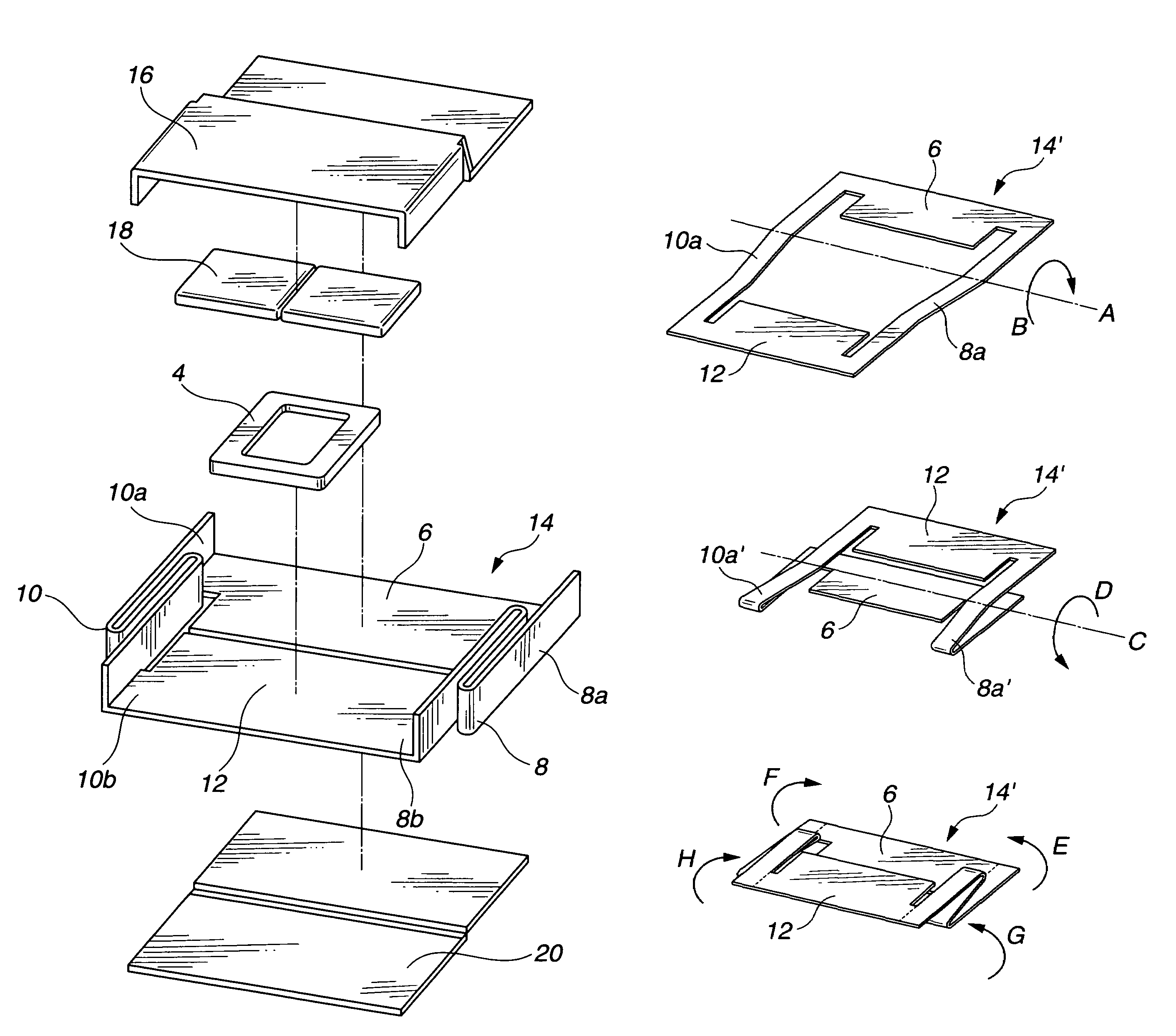
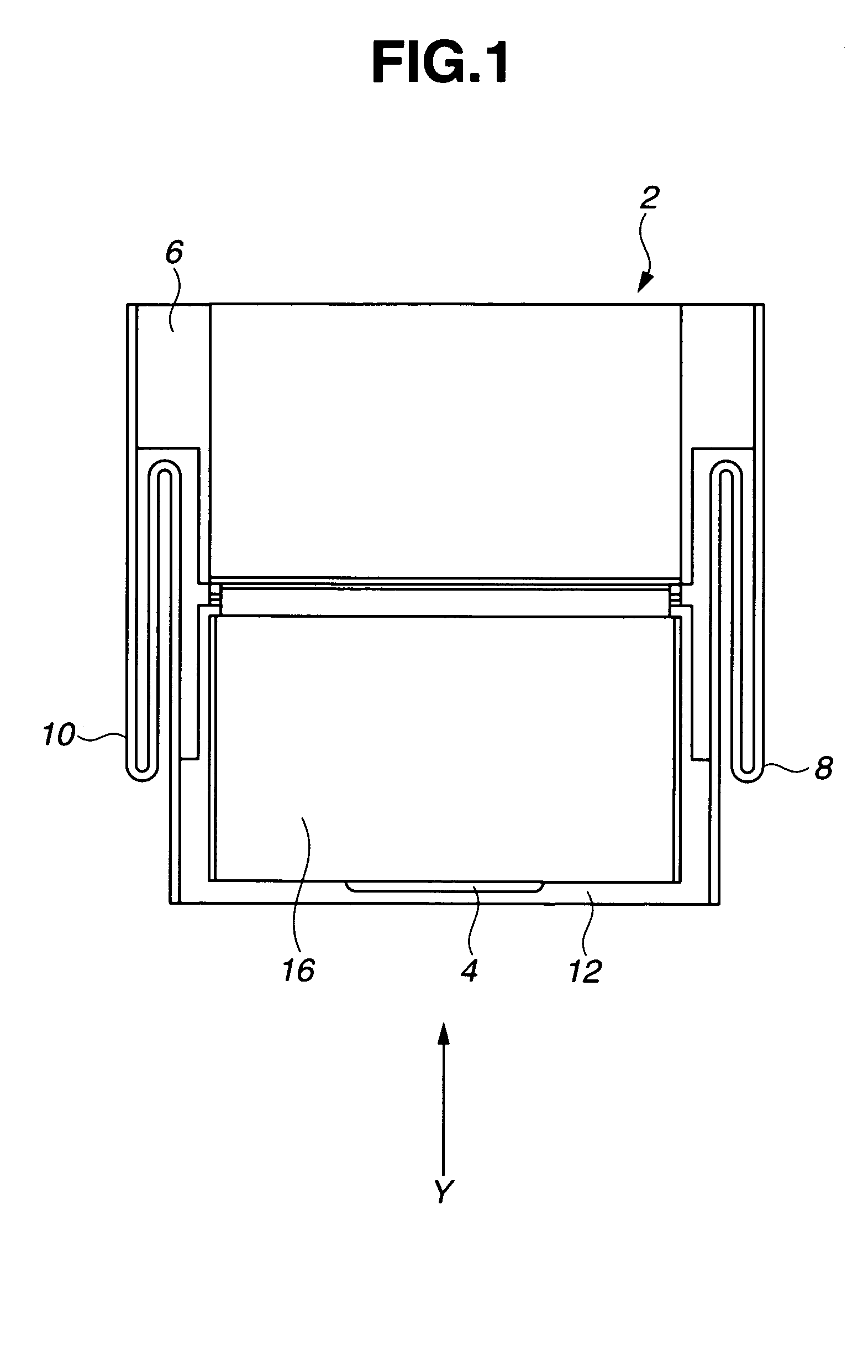
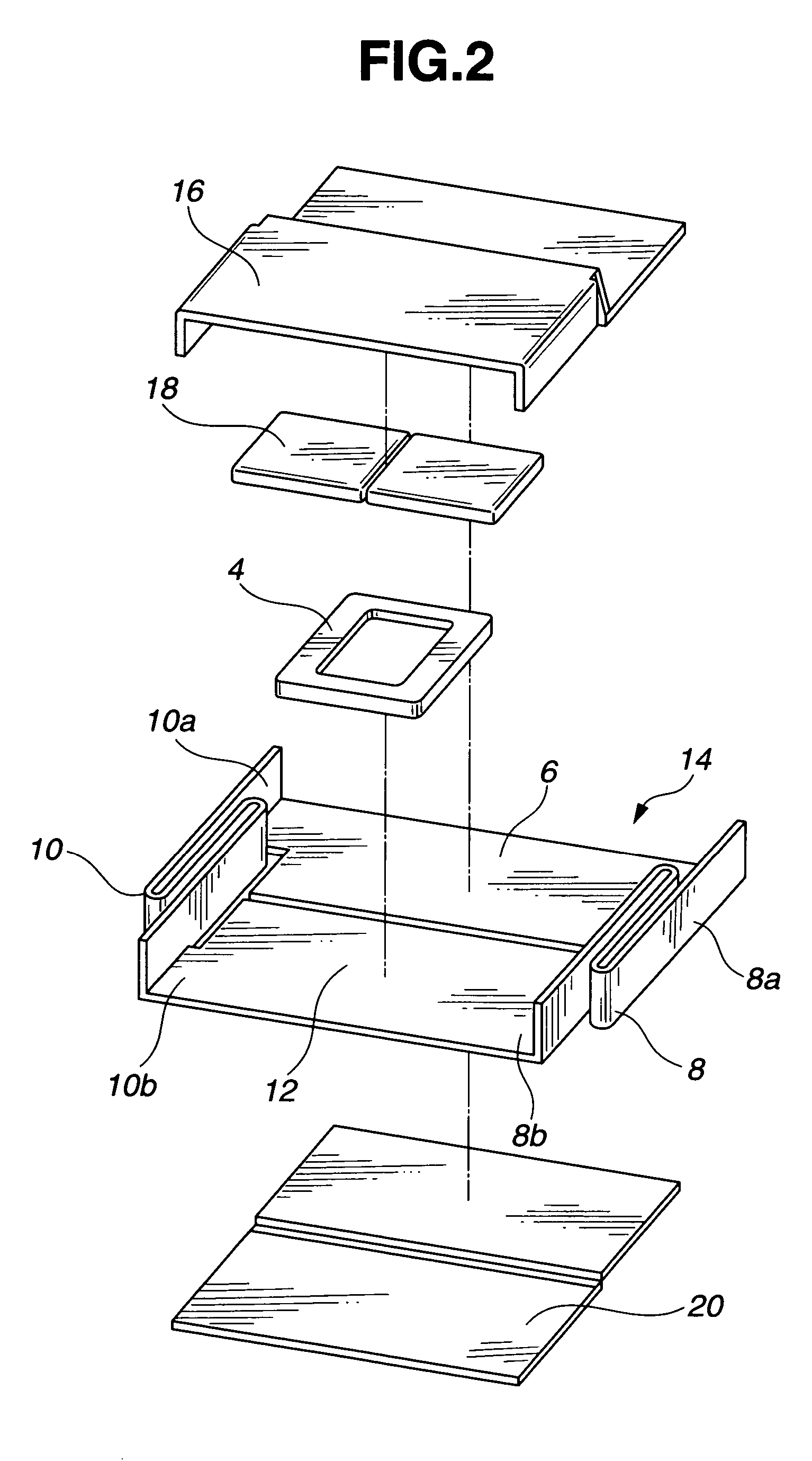
[0031]FIGS. 1 and 2 are plan and perspective exploded views of a direct-acting actuator 2 according to one embodiment of the invention, respectively. For the sake of clarity, wires for supplying electric power to a coil are not shown. The actuator 2 includes a stator section or member 16, a member 14, and an optional yoke 20. The member 14 includes a stator attachment section 6, micro-beams 8, 10, and a rotor section 12. Attached to the rotor section 12 is a coil 4. Disposed in the stator section 16 is a permanent magnet 18. The stator section 16 is preferably made of a ferromagnetic material for helping form a magnetic circuit. The auxiliary yoke 20 made of a ferromagnetic material may be attached, if necessary, for enhancing the efficiency of the magnetic circuit. The member 14 (which includes the stator attachment section 6, the micro-beams 8, 10, and the rotor section 12), the stator section 16, and the auxiliary yoke 20 are assembled and secured to an apparatus that carries the...


PUM

PropertyMeasurementUnit
heightaaaaaaaaaa
lengthaaaaaaaaaa
widthaaaaaaaaaa

Abstract

A direct-acting actuator is provided comprising a stator section (16), an attachment section (6) secured to the stator section, micro-beams (8, 10) extending from the attachment section, a rotor section (12) supported for swing motion by the micro-beams, a permanent magnet (18) disposed in the stator section, and a coil (4) disposed in the rotor section. Electric current is conducted through the coil in the magnetic field created by the permanent magnet for causing the micro-beams to be displaced for inducing swing motion of the rotor section. The actuator can be assembled to a small size, typically a width of 1-10 mm, a length of 1-10 mm, and a height of 0.1-5 mm.

Description

CROSS-REFERENCE TO RELATED APPLICATION[0001]This non-provisional application claims priority under 35 U.S.C. §119(a) on Patent Application No. 2003-408859 filed in Japan on Dec. 8, 2003, the entire contents of which are hereby incorporated by reference.TECHNICAL FIELD[0002]This invention relates to a small-size direct-acting actuator.BACKGROUND ART[0003]The recent advance of the semiconductor fabrication technology has made it possible to construct ultra-fine structures of the micrometer order. Triggered by the advanced processing technology, efforts are being made on the research and development of so-called micro-machines. The actuator which is one of elemental devices of the micro-machine is of great concern.[0004]From the movement aspect, the microactuator is generally divided into rotary and direct-acting types. Since the direct-acting type has a very simple structure, most research works address direct-acting actuators. From the driving principle, the microactuator is generall...

Claims


Application Information

Patent Timeline
Patent Type & Authority Patents(United States)
IPC IPC(8): G11B21/10G11B21/21H01F7/122H01F7/14H02K33/06H02K41/035
CPCH02K33/06H01F7/122H01F7/14H01F2007/068
Inventor NAKAMURA, HAJIMEMINOWA, TAKEHISA
Owner SHIN ETSU CHEM IND CO LTD
Why Eureka
Try Eureka