Estimating channel impulse response and equalizer coefficients in UWB communication systems

a communication system and channel impulse technology, applied in the field of radio communication systems, can solve the problems of prohibitively expensive a/d converters that can process 10,000,000,000 samples per second, prohibitively expensive sampling and a/d converting at 10 g samples/s,

Inactive Publication Date: 2008-04-08
MITSUBISHI ELECTRIC RES LAB INC
View PDF17 Cites 12 Cited by
  • Summary
  • Abstract
  • Description
  • Claims
  • Application Information

AI Technical Summary

Benefits of technology

[0019]After the channel has been estimated, the weights for the rake receiver used for the data reception are determined. Final

Problems solved by technology

However, it is a challenge to realize UWB modulation schemes that increase data throughput while minimizing errors in dense multi-path environments.
However, other users and out-of-band interferers might be transmitting while the single training

Method used


Image

  • Estimating channel impulse response and equalizer coefficients in UWB communication systems
  • Estimating channel impulse response and equalizer coefficients in UWB communication systems
  • Estimating channel impulse response and equalizer coefficients in UWB communication systems

Examples


Embodiment Construction

System Structure and Operation

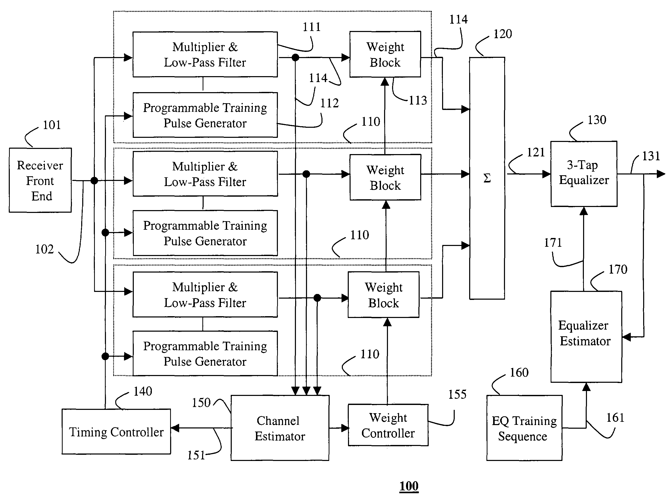
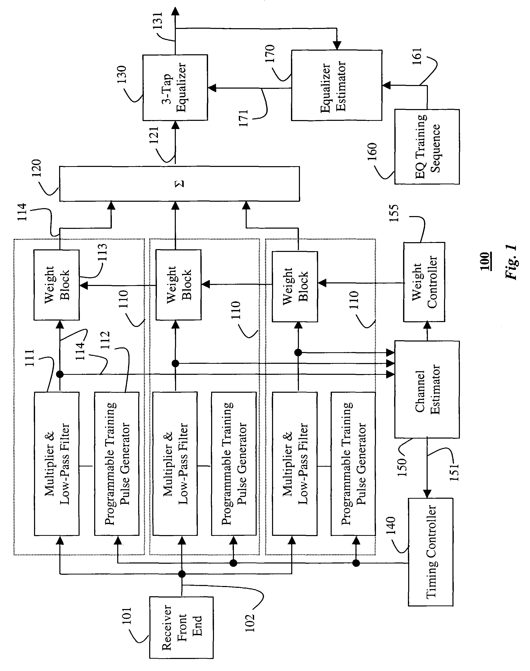
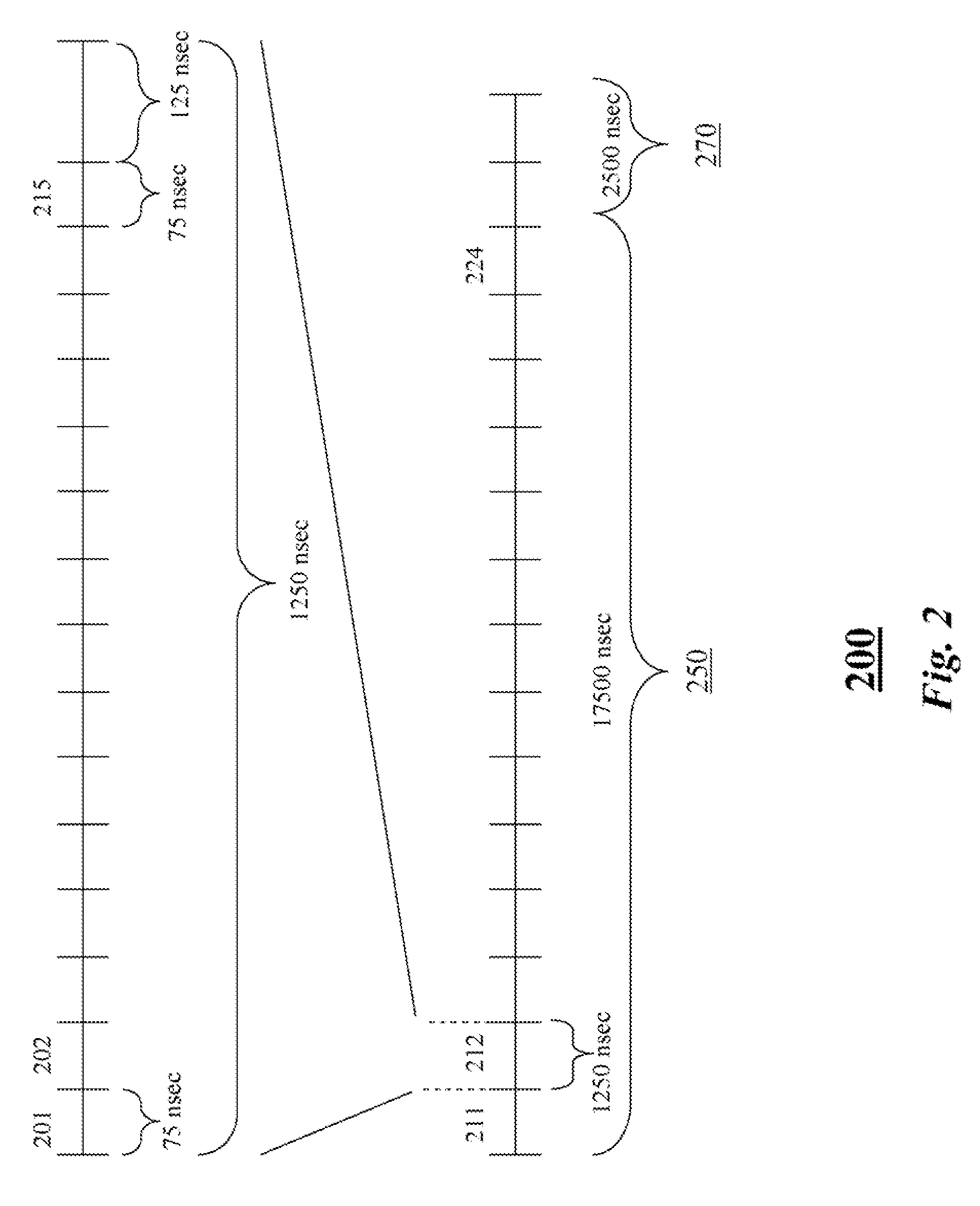
[0029]FIG. 6 shows a UWB system according to the invention. The system includes a transmitter 601 and a rake-like receiver 100 connected via a wireless channel 603. Both the transmitter and the receiver include a clock (CLCK) 604. The clocks are synchronized 605 to each other. The details of how this is achieved can vary, see, e.g., Meyr et al., Synchronization, Channel Estimation, and Signal Processing, Volume 2, Digital Communication Receivers, Wiley, 1997. The transmitter sends m training sequences 200 as described in detail below. The pulses of the training sequences are modulated at a chip rate.

[0030]As shown in FIG. 7, each of the m training sequences 200 is passed, in parallel, through multiple correlators 701 (rake fingers) of the receiver 100. Parallel “sample and hold” circuits 702 sample each received training circuits at multiple delay points with fixed offsets to obtain at least one (k=1) sample for each training sequence. It should be note...


PUM


Abstract

A method estimates a channel impulse response in an ultra wide bandwidth (UWB) system. Multiple training sequences modulated at a chip rate are received. Each training sequence is sampled by parallel with multiple correlators at sampling rate substantially slower than the chip rate to obtain a samples over a time interval of the impulse response at a resolution substantially equal to the chip rate, and then estimating the channel impulse response from these samples.

Description

CROSS-REFERENCE TO RELATED APPLICATIONS[0001]A claim of priority is made to U.S. Provisional Patent Application Ser. No. 60 / 451,528, filed Mar. 3, 2003, entitled “Channel Estimation and Equalizer Coefficient Estimation for UWB Radio Communication Systems.”FIELD OF THE INVENTION[0002]The present invention relates generally to radio communication systems, and more particularly to channel and equalization estimation in an ultra wide bandwidth communications systems.BACKGROUND OF THE INVENTION[0003]With the release of the “First Report and Order,” Feb. 14, 2002, by the Federal Communications Commission (FCC), interest in ultra wide bandwidth (UWB) communication systems has increased. The IEEE 802.15 standards organization, which is responsible for Personal Area Networks, has established a task group, TG3a, to standardize a high-data-rate physical layer based on UWB.[0004]Ultra wide bandwidth (UWB) communication systems transmit and receive extremely short electromagnetic energy impulses...

Claims


Application Information

Patent Timeline
IPC IPC(8): H04L27/06H04B1/00H04B1/69H04L1/20H04L25/02H04L25/03
CPCH04B1/71637H04B1/719H04L1/203H04L25/0226H04L25/03012H04L25/0212H04B1/709H04L2025/03484
Inventor MOLISCH, ANDREASLI, YEZHANG, JINYUN
Owner MITSUBISHI ELECTRIC RES LAB INC
Why Eureka
Try Eureka