Supercharge Your Innovation With Domain-Expert AI Agents!

Control system for a linear propulsor array

a control system and propulsor array technology, applied in the field of propulsion systems, can solve the problems of unproven system, unreliability, and inability to meet the requirements of micro-robots for biological applications, and achieve the effect of improving the accuracy of control system

Inactive Publication Date: 2008-04-15
IBM CORP
View PDF17 Cites 9 Cited by
  • Summary
  • Abstract
  • Description
  • Claims
  • Application Information

AI Technical Summary

Benefits of technology

The invention is a control system for a scalable, configurable "propulsor" system. This system is made up of individual propulsors that work together to create a continuous control surface that moves in a fluid. Each propulsor is controlled by computer-controlled actuators, which cause the surface to move in different ways. The system can also have optional actuators that can refine the surface shape. Overall, this invention allows for the creation of a flexible and customizable control system for propulsor systems.

Problems solved by technology

But developing micro-robots for biological applications is replete with novel challenges, not the least of which is developing a biologically safe propulsion system that can operate while submersed in unusual fluid media—such as blood, saliva, or even spinal fluid—at the micron scale.
But as the authors confess, “This system contains components of many different scales, significantly increasing the difficulty of fabrication.” Id.
Moreover, while theoretically provocative and ostensibly safe to biological systems, the system proposed by Edd et al. is unproven and, thus, potentially unreliable.
But converting such devices into micro- or nano-scale devices for biological applications is problematic.
Propellers and pumps, for instance, generally require bearings and seals that are difficult to manufacture or assemble at such small scales.
Propellers and pumps also are a potential hazard to delicate biological systems, and additional care must be taken when designing systems for biological applications.
Pumps, in particular, are susceptible to taking in and destroying objects from surrounding fluid.
And while propellers are vulnerable to damage from foreign objects in a fluid, the more significant concern in a biological application is the potential damage that a propeller could cause to objects in or bounding the fluid.

Method used


Image

  • Control system for a linear propulsor array
  • Control system for a linear propulsor array
  • Control system for a linear propulsor array

Examples


Embodiment Construction

[0029]The invention described herein comprises a “linear propulsor array,” which acts upon any working fluid to cause a reactive force. Mounted on a mobile device, a linear propulsor array generates a reactive force in the working fluid that propels the device through the fluid. Alternatively mounted on a stationary platform, a linear propulsor array generates a reactive force that drives the fluid surrounding the array.

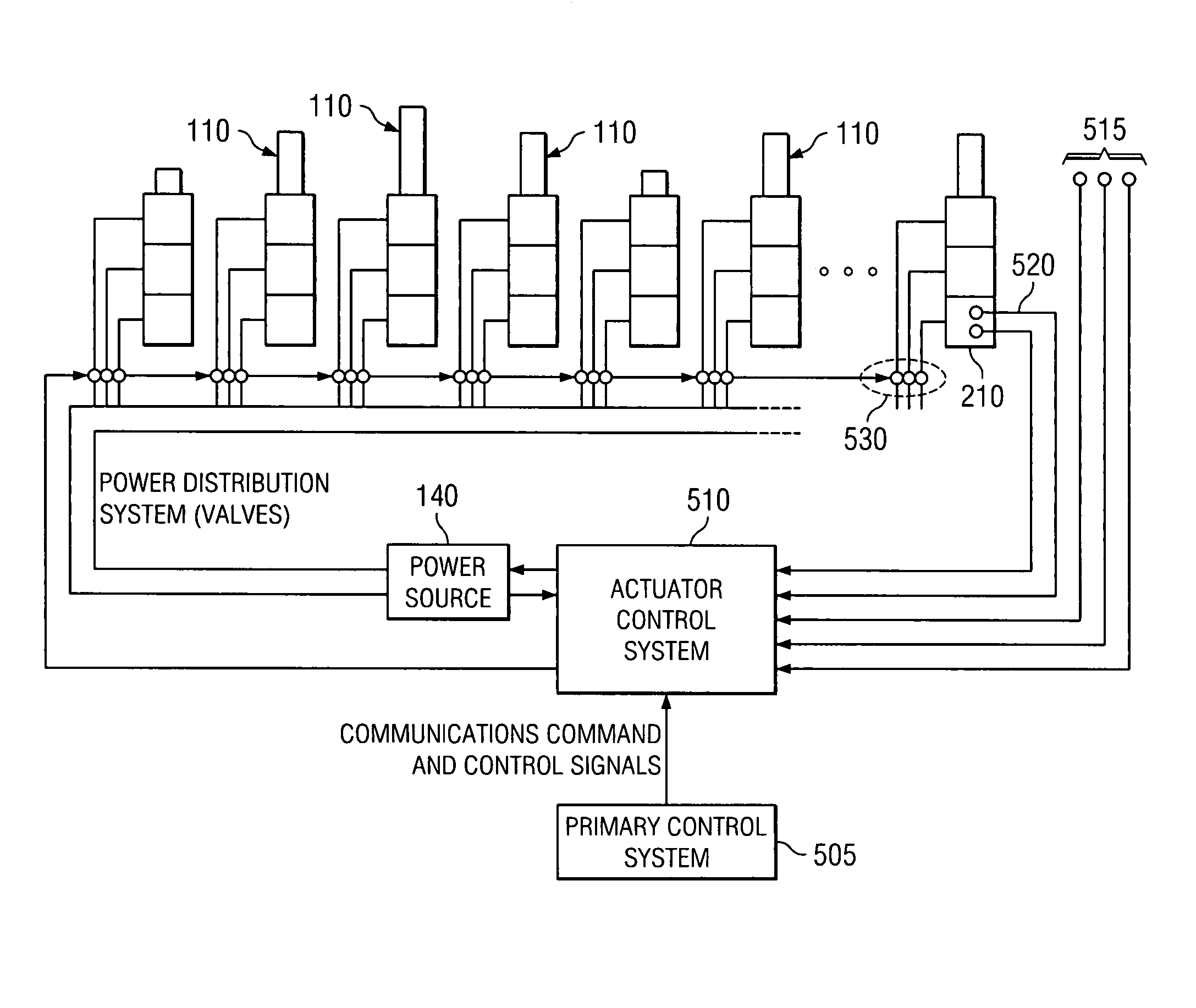
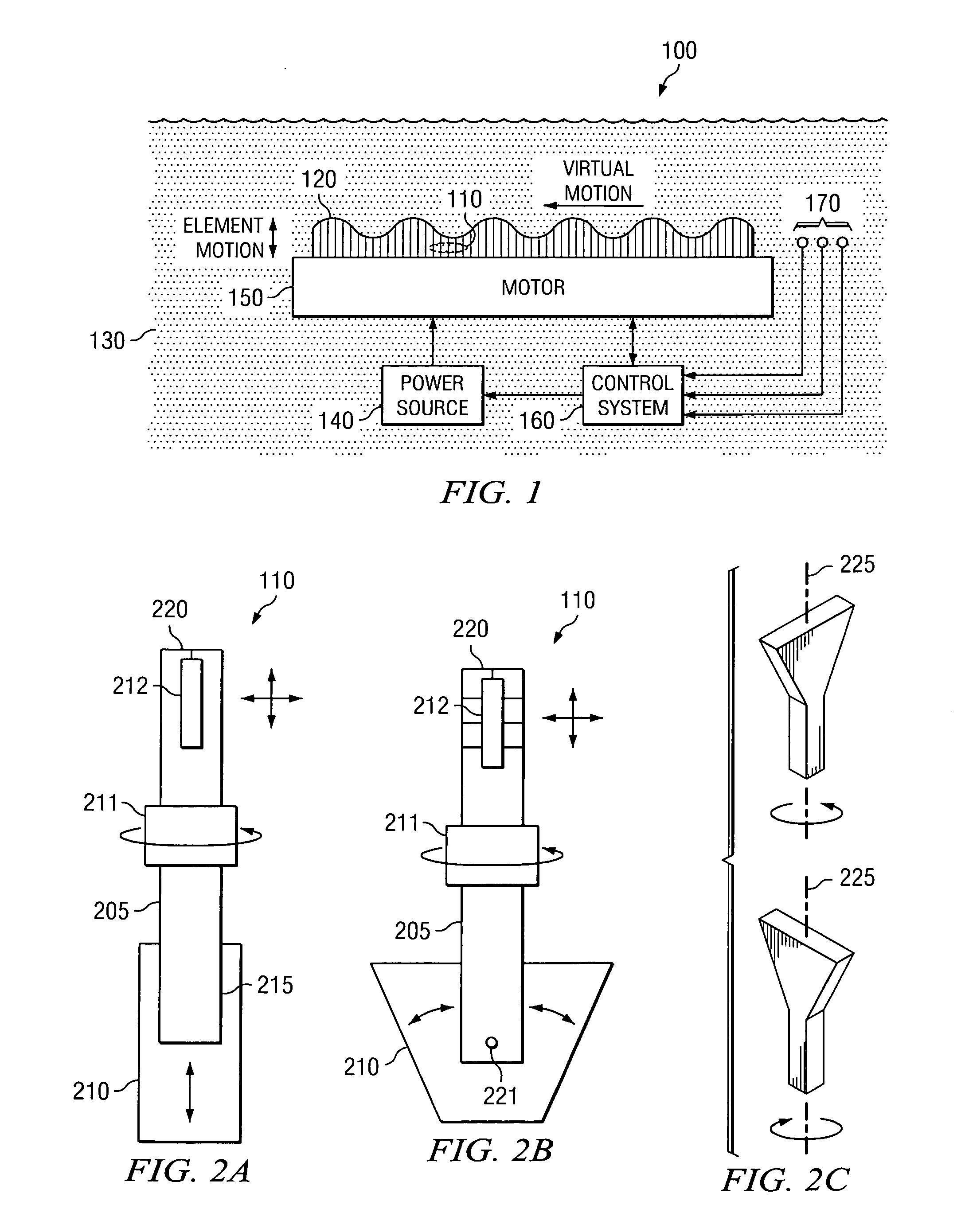
[0030]FIG. 1 highlights some of the broad features of an exemplary linear propulsor array. Linear propulsor array 100 is an assembly of individual “propulsors”110 that act in concert to form a substantially continuous control surface 120 that undulates in working fluid 130. Propulsor array 100 is powered by power source 140 and driven by motor 150 under the control of control system 160, which receives data from various sensors 170. A propulsor 110 generally comprises a bar 205 and a primary actuator 210 coupled to bar 205 on base 215, as shown in FIG. 2A.
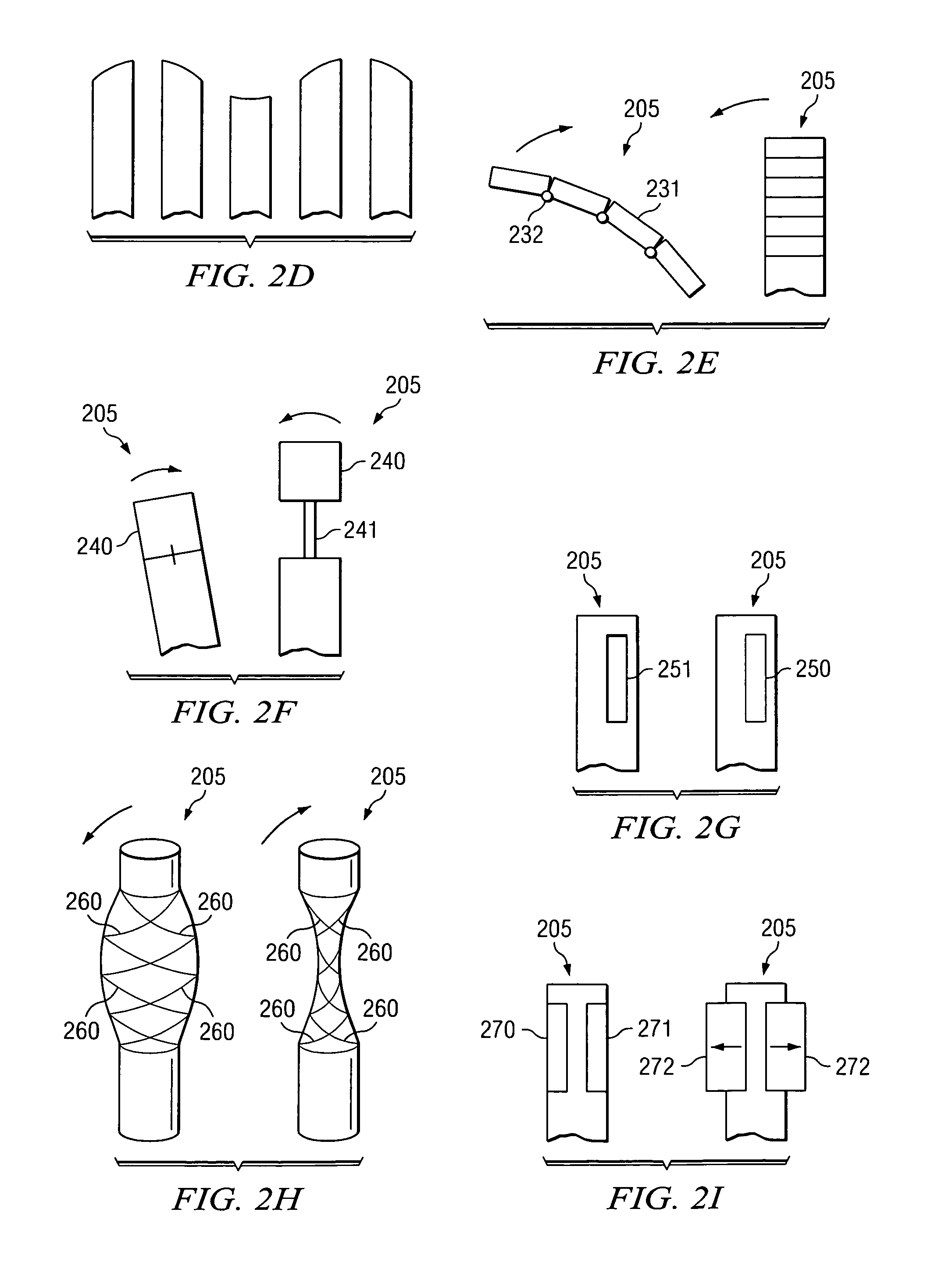
[0031]Bar 2...


PUM


Abstract

The invention comprises a method of using a scalable, configurable “propulsorsystem to move and navigate a submersible device through a fluid medium. A propulsor system is an assembly of individual propulsors that act in concert to form a substantially continuous control surface that undulates in a working fluid. Each propulsor is driven and configured by computer-controlled actuators so that the control surface undulates in various wave forms. Optional actuators that may refine the surface shape include an “orientation” actuator that drives rotation about the propulsor's longitudinal axis, and a “geometry” actuator that controls each propulsor's geometric configuration.

Description

CROSS-REFERENCE TO RELATED APPLICATION[0001]The present invention is related to the subject matter of U.S. patent applications Ser. No. 11 / 049.897 (now U.S. Pat. No. 7,204,731), 11 / 050,593 (now U.S. Pat. No. 7,090,548), and 11 / 050,601 (now U.S. Pat. No. 7,244,151), incorporated herein by reference.FIELD OF THE INVENTION[0002]The present invention generally is related to propulsion systems operable in a fluid medium, and, more specifically, to a control system for a traveling wave propulsion system.BACKGROUND OF THE INVENTION[0003]Within the last hunched years, autonomous machines that perform useful tasks have emerged slowly from the realm of science fiction into a field of infinite practical application. More commonly known as “robots,” such machines have been used for industrial automation, space exploration, and even cleaning house. Advances in robotics and miniaturization technology in recent years also have brought the possibility of micro-scale robots to the brink of reality. ...

Claims


Application Information

Patent Timeline
Patent Type & Authority Patents(United States)
IPC IPC(8): B63H1/37
CPCA61B19/22B63G8/08B63H1/00B63H19/00G05D19/02A61B2019/2249A61B34/70A61B34/72
Inventor GUSLER, CARL PHILLIP
Owner IBM CORP
Features
  • R&D
  • Intellectual Property
  • Life Sciences
  • Materials
  • Tech Scout
  • Unparalleled Data Quality
  • Higher Quality Content
  • 60% Fewer Hallucinations
Learn More