
Deheader valve installation system and method

a deheader valve and installation system technology, applied in the direction of valve housings, charging-discharging device combinations, mechanical equipment, etc., can solve the problems of falling coke, heavy equipment to fall, and the process of deheading the coke drum can be extremely dangerous, and achieve the effect of bi-directional horizontal transition of the deheader valv

Inactive Publication Date: 2008-04-15
CURTIS WRIGHT FLOW CORP
View PDF9 Cites 2 Cited by
  • Summary
  • Abstract
  • Description
  • Claims
  • Application Information

AI Technical Summary

Benefits of technology

"The present invention is a dynamic deheader valve installation system that allows for the safe and efficient installation and removal of a deheader valve onto a pressure vessel. The system includes a fixed support structure, a valve carriage, an elevation adjustment assembly, and a horizontal transfer assembly. The elevation adjustment assembly allows for independent and adjustable vertical positioning of the valve carriage and the deheader valve, while the horizontal transfer assembly enables bi-directional and horizontal transitioning of the deheader valve. The system also includes a method for providing continued support of the closure during installation and removal from the pressure vessel. The technical effects of the invention include improved safety and efficiency in installing and removing closures on pressure vessels, as well as increased efficiency and safety in high temperature, high pressure environments."

Problems solved by technology

This process of de-heading the coke drum can be extremely dangerous for several reasons.
To mention only a few, the cooling water introduced into the hot drums prior to the removal of the bottom head becomes extremely hot and could leak from the loosened head and scald surrounding operators, the load of un-drained water and loose coke within the drum may exceed the limits of the support system and cause heavy equipment to fall, positioning the chute and necessary removal of the flanges or heads is done with operators who are in close proximity to the drums, potentially falling coke may injure workers as the heads are removed, and operating personnel may be exposed to finely divided coke particles, steam, hot water and noxious gases, when the drum is opened.
Indeed several fatalities occur each year as a result of this manufacturing process.
This is extremely dangerous due to the manual labor requirements.
Each of these prior art devices share common deficiencies in that they are incapable of providing simple, efficient, and safe solutions to the de-heading of a coke drum.
This creates an extreme hazard to workers and provides an inefficient and time consuming procedure.
Removal of the head unit increases the chance for accident, while at the same time increases human involvement as the head unit must be properly placed on the coke drum each time despite the automation involved.
In addition, a large amount of floor space is required to accommodate those assemblies and devices that automate the removal and lifting of the head unit from the coke drum.
Finally, such devices and systems may not be operable in an environment where there the bottom headroom is less than the diameter of the bottom head.
Obviously, there are many technical challenges associated with accomplishing this goal.
Presently, one of the major roadblocks of the total automation concept is the coke drum unheading methods used.
Whether drum unheading is done manually, or by any one of the above discussed prior art systems and devices that are currently available, there is a significant hands on component required in the process.
As is well known in the industry, the hands on component of unheading always was, and remains today, very hazardous for operating personnel.

Method used


Image

  • Deheader valve installation system and method
  • Deheader valve installation system and method
  • Deheader valve installation system and method

Examples


Embodiment Construction

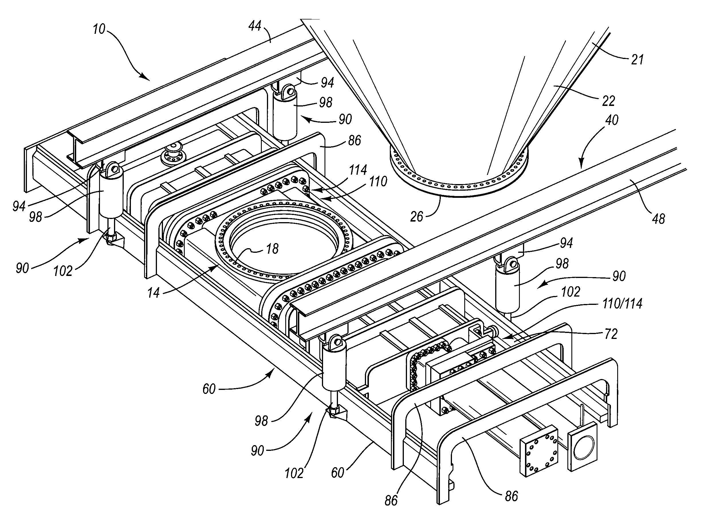
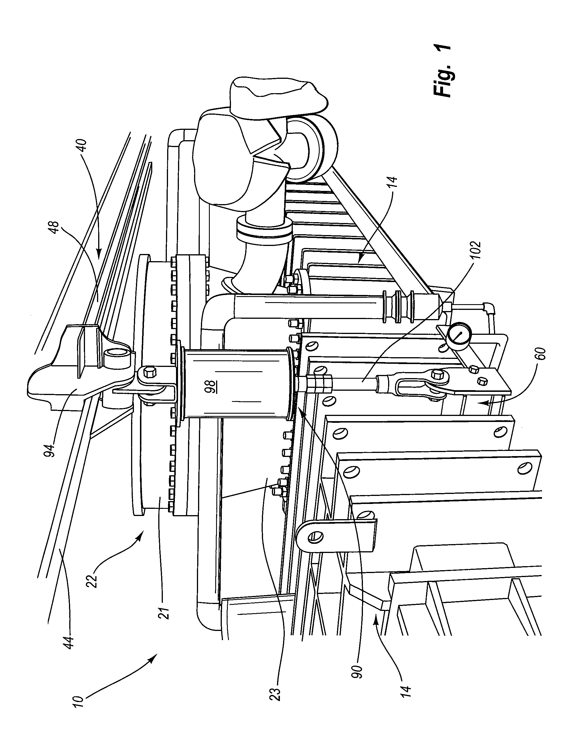
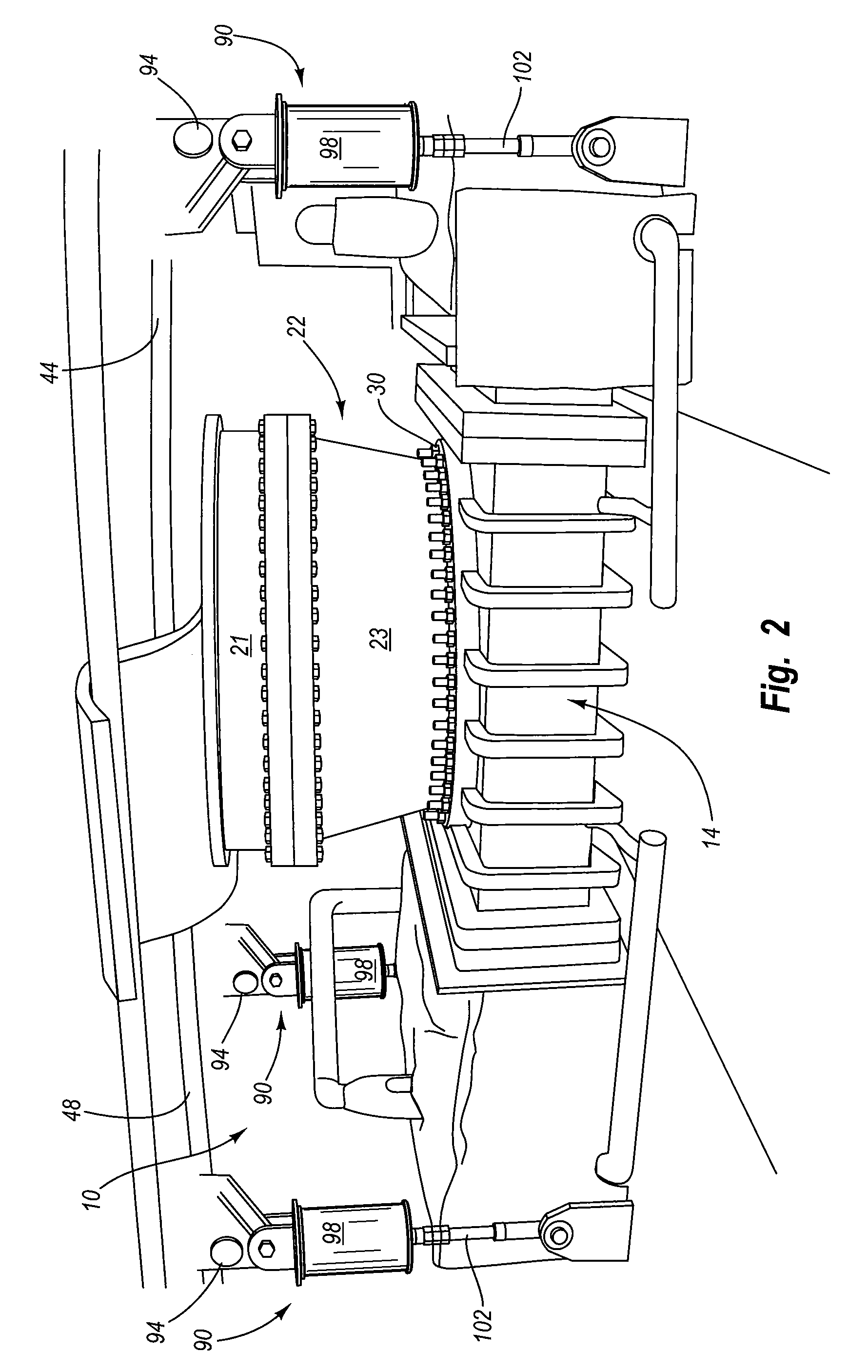
[0036]It will be readily understood that the components of the present invention, as generally described and illustrated in the figures herein, could be arranged and designed in a wide variety of different configurations. Thus, the following more detailed description of the embodiments of the system and method of the present invention, and represented in FIGS. 1 through 5, is not intended to limit the scope of the invention, as claimed, but is merely representative of the presently preferred embodiments of the invention.

[0037]The presently preferred embodiments of the invention will be best understood by reference to the drawings wherein like parts are designated by like numerals throughout.

[0038]The present invention describes a method and system for supporting a deheader valve during installation onto a pressure vessel, and also when the deheader valve is decoupled from the pressure vessel for maintenance or other purposes. For clarification and ease of reading, the following more...


PUM

PropertyMeasurementUnit
thermal cracking temperaturesaaaaaaaaaa
heightaaaaaaaaaa
heightaaaaaaaaaa

Abstract

The present invention features an installation system for facilitating the installation and removal of a closure onto and from a pressure vessel, respectively. The installation system comprises a fixed support structure constructed proximate a pressure vessel; a carriage dynamically and continuously supported by the fixed support structure, wherein the carriage also dynamically and adjustably supports a closure, such as a header or a deheader valve, in a continuous manner; an elevation adjustment assembly allowing the carriage and the closure to move in a vertical manner relative to the fixed support structure and the pressure vessel; and a horizontal transfer assembly that dynamically couples the closure to the carriage to enable horizontal, bidirectional transitioning of the closure relative to the carriage. The elevation adjustment assembly and the horizontal transfer assembly work in harmony together to provide both approximate and precision vector positioning of the closure to enable parallel and concentric alignment with the pressure vessel. In this manner, the closure may be installed and removed from the pressure vessel in a much safer and more efficient manner.

Description

RELATED APPLICATIONS[0001]This application claims priority to U.S. patent application Ser. No. 60 / 527,937 filed Dec. 8, 2003, entitled “Deheader Valve Installation System and Method.”BACKGROUND[0002]1. Field of the Invention[0003]The present invention relates to deheader valves as designed for connection to corresponding pressure vessels within high temperature, high pressure environments, and more particularly to methods and systems for installing a deheader valve onto or removing a deheader valve from a pressure vessel, such as a coke drum or intermediate spool, operable within a delayed coking system.[0004]2. Background of the Invention and Related Art[0005]In the hydrocarbon processing industry, many refineries recover valuable products from the heavy residual oil that remains after refining operations are completed. This recovery process is known as delayed coking and produces valuable distillates and coke in large vessels or coke drums. Coke drums are usually in operation in p...

Claims


Application Information

Patent Timeline
Patent Type & Authority Patents(United States)
IPC IPC(8): C10B25/00C10B1/04C10B25/10F16K27/04
CPCC10B1/04C10B25/10F16K27/044
Inventor LAH, RUBEN F.
Owner CURTIS WRIGHT FLOW CORP
Learn More