Power efficient, high bandwidth communication using multi-signal-differential channels

a multi-signal, high-bandwidth technology, applied in the field of electronic signaling systems and methods, can solve the problems of differentially encoded busses having a significant disadvantage in high-speed communication links, large gap, and large area and pad count of differentially encoded busses, so as to increase the code density of equivalent differentially encoded bus structures and save power, area and pad count.

Active Publication Date: 2008-04-15
PITTSBURGH UNIV OF
View PDF3 Cites 159 Cited by
  • Summary
  • Abstract
  • Description
  • Claims
  • Application Information

AI Technical Summary

Benefits of technology

[0014]In accordance with at least one preferred embodiment, the present invention provides an alternative to differential signaling for channel encoding of high-speed data bus applications. The method, called Multi-Bit Differential Signaling (MBDS), retains the noise and loss advantages of conventional differential signaling, but increases the code density of equivalent differentially encoded bus structures. By exploiting a larger set of assignable code symbols, an MBDS encoded bus can send the same information across fewer physical connections than a differentially-encoded bus with the same bit width. The result is a substantial savings in power, area and pad count.

Problems solved by technology

This gap continues to widen as CMOS technology advances faster than PCB fabrication and materials technology and has become a substantial bottleneck in overall system performance.
Accordingly, differentially encoded busses have a significant disadvantage in high-speed communication links.
The disadvantage of differential signaling stems from its low code density—using only half of the signaling capacity of the available transmission lines.
Although described as such, this problem with differential signaling is not limited to proposed chip-to-chip link standards within multi-chip-modules and printed circuit boards.
As lower supply voltage drives down transistor thresholds, leakage current increases significantly in the repeating buffers required.
Simultaneously, higher bandwidth and smaller feature size has decreased the distance between these buffers, increasing their number and thus the total power lost to leakage current.

Method used


Image

  • Power efficient, high bandwidth communication using multi-signal-differential channels
  • Power efficient, high bandwidth communication using multi-signal-differential channels
  • Power efficient, high bandwidth communication using multi-signal-differential channels

Examples


Embodiment Construction

[0025]It is to be understood that the figures and descriptions of the present invention have been simplified to illustrate elements that are relevant for a clear understanding of the invention, while eliminating, for purposes of clarity, other elements that may be well known. Those of ordinary skill in the art will recognize that other elements are desirable and / or required in order to implement the present invention. However, because such elements are well known in the art, and because they do not facilitate a better understanding of the present invention, a discussion of such elements is not provided herein. The detailed description will be provided hereinbelow with reference to the attached drawings.

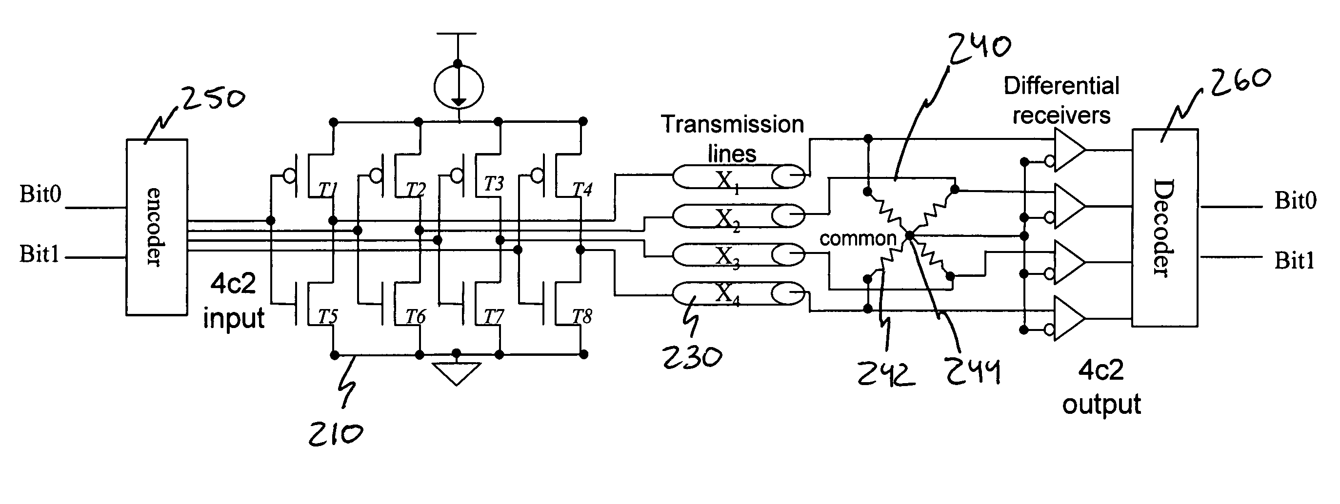
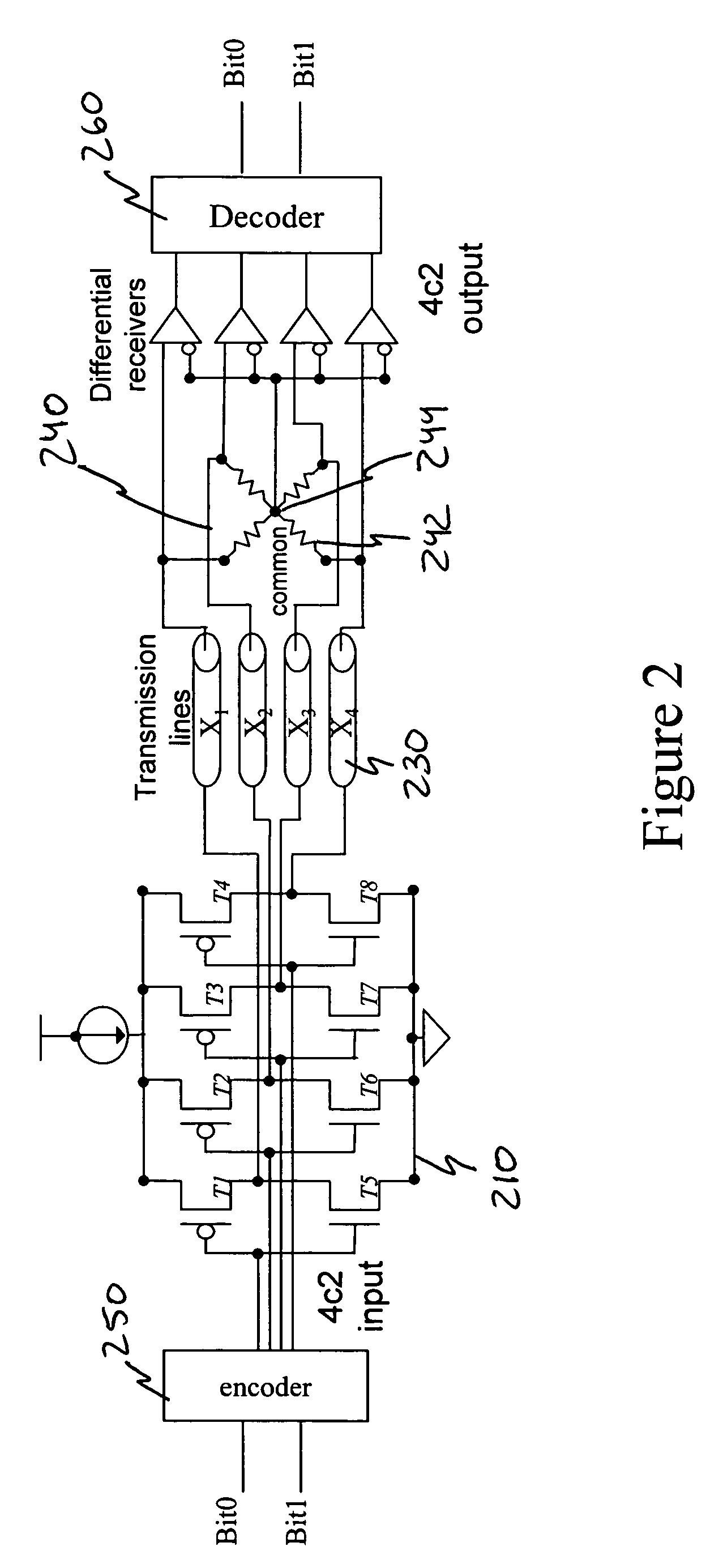
[0026]As briefly described above, the present invention utilizes a multi-bit differential signaling (MBDS) methodology applied to an improved communications link topology to increase code density and decrease power consumption without sacrificing the performance expected of convention...


PUM


Abstract

A low-power, area and pin efficient signaling alternative to serial differential links used for chip-to-chip, backplane, optical and other signaling applications. The multi-bit differential signaling (MBDS) generally comprises a driver and link termination network design coupled with a coding system based on n choose M (nCm) coding. MBDS has comparable electrical characteristics to conventional low-voltage differential signaling (LVDS) and is fully compatible with existing LVDS receivers in point-to-point and multi-point bus topologies. However, MBDS uses up to 40% less power, with up to 33% fewer I/O pads than equivalent LVDS links.

Description

CROSS-REFERENCE TO RELATED APPLICATIONS[0001]This application claims the benefit under 35 U.S.C. 119(e) of the earlier filing date of U.S. Provisional Patent Application No. 60 / 496,999 filed on Aug. 20, 2003.BACKGROUND OF THE INVENTION[0002]1. Field of the Invention[0003]The present invention relates generally to systems and methods for electronic signaling, and, more particularly, the present invention is directed to a multi-bit differential signaling alternative to traditional differential signaling methodologies.[0004]2. Description of the Background[0005]Electrical communication links have long embraced the use of differential signaling for low noise and high bandwidth data transmission. For example, high performance data channels are of increasing importance for applications such as chip-to-chip PCB (PC Board) interconnect and disk drive data channels as smaller features and lower voltages drive the economics of CMOS design away from traditional bit-per-wire I / O. Although the r...

Claims


Application Information

Patent Timeline
Patent Type & Authority Patents(United States)
IPC IPC(8): H03M5/00
CPCH03M5/00
Inventor CHIARULLI, DONALD M.LEVITAN, STEVEN P.
Owner PITTSBURGH UNIV OF
Why Eureka
Try Eureka