
Raised access floor

a raised access floor and access door technology, applied in the field can solve the problems of reducing the storage capacity of relatively heavy equipment, limiting the weight of many raised access floors, and limiting the number of raised access floors, so as to facilitate the insertion of the tab, reduce the bowing of the top surface, and facilitate manufacturing.

Inactive Publication Date: 2008-04-22
AIRTEX MFG LLLP
View PDF25 Cites 86 Cited by
  • Summary
  • Abstract
  • Description
  • Claims
  • Application Information

AI Technical Summary

Benefits of technology

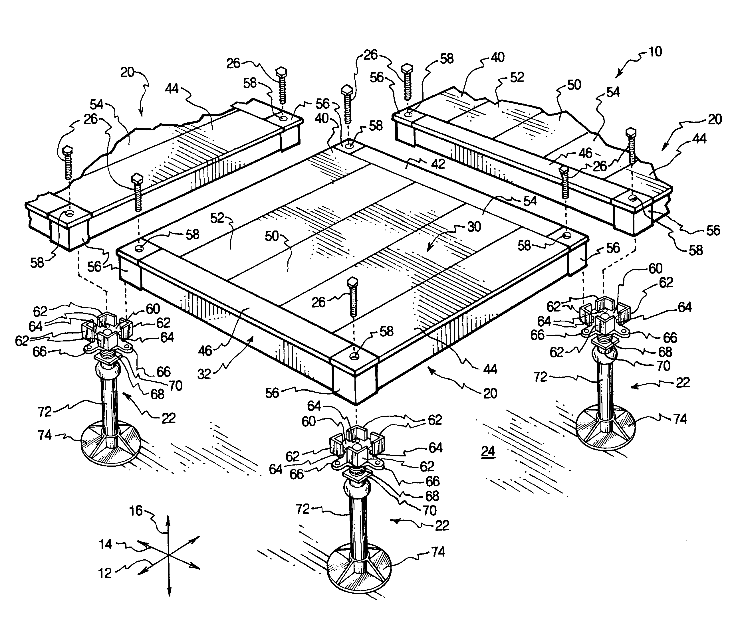
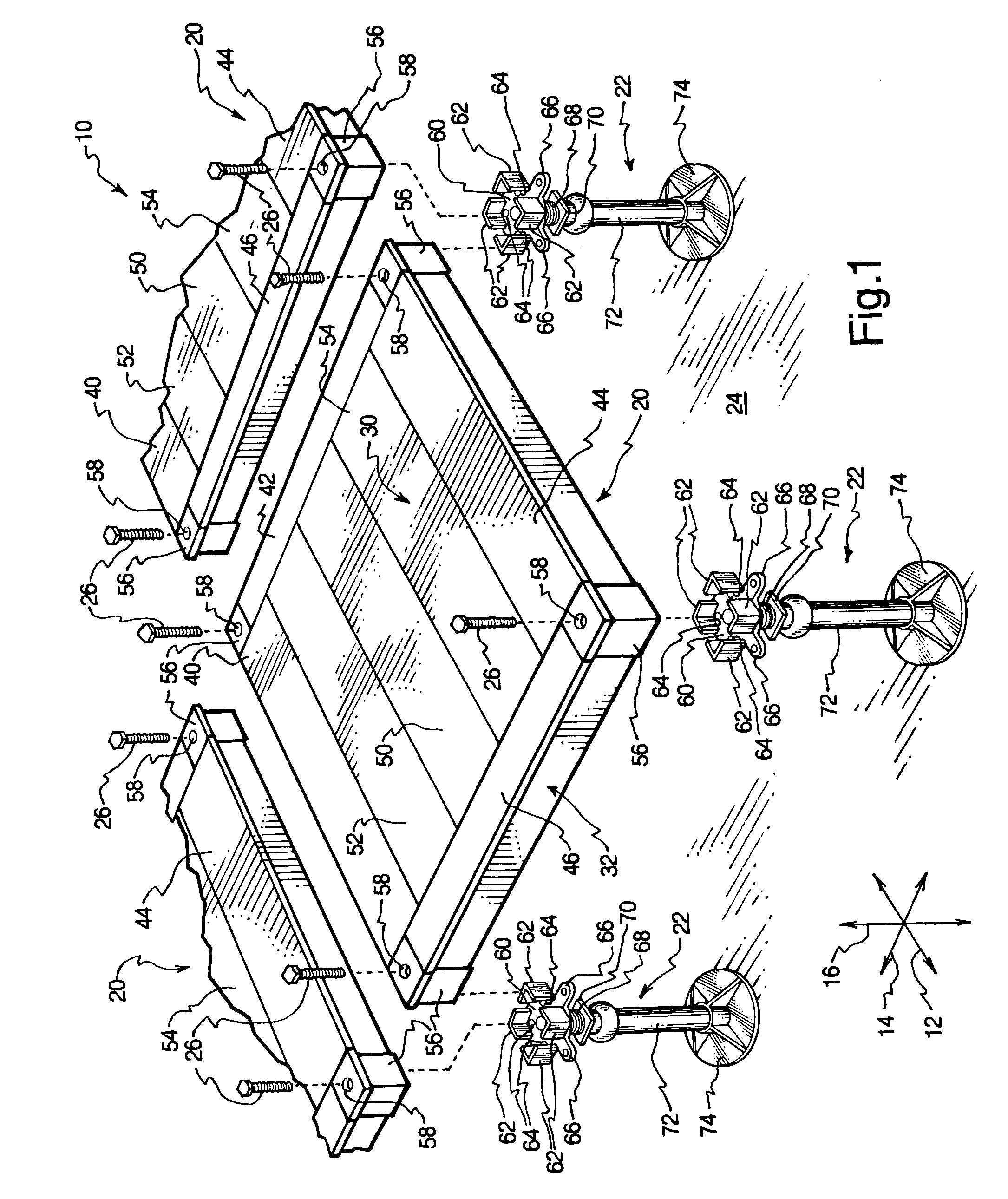
[0019]Each pedestal also has a threaded shank and a nut that threadably engages the shank in such a manner that the shank can raise or lower with respect to a stem to adjust the height of the platform above the support surface. The stem is attached to a foot that has a substantial area in contact with the support surface to enhance the stability of the pedestal. The panels are disposed to rest on the platforms of the pedestals and attached to the pedestals via the screws to form a relatively continuous surface that provides easy access to the region between the support surface and the panels.
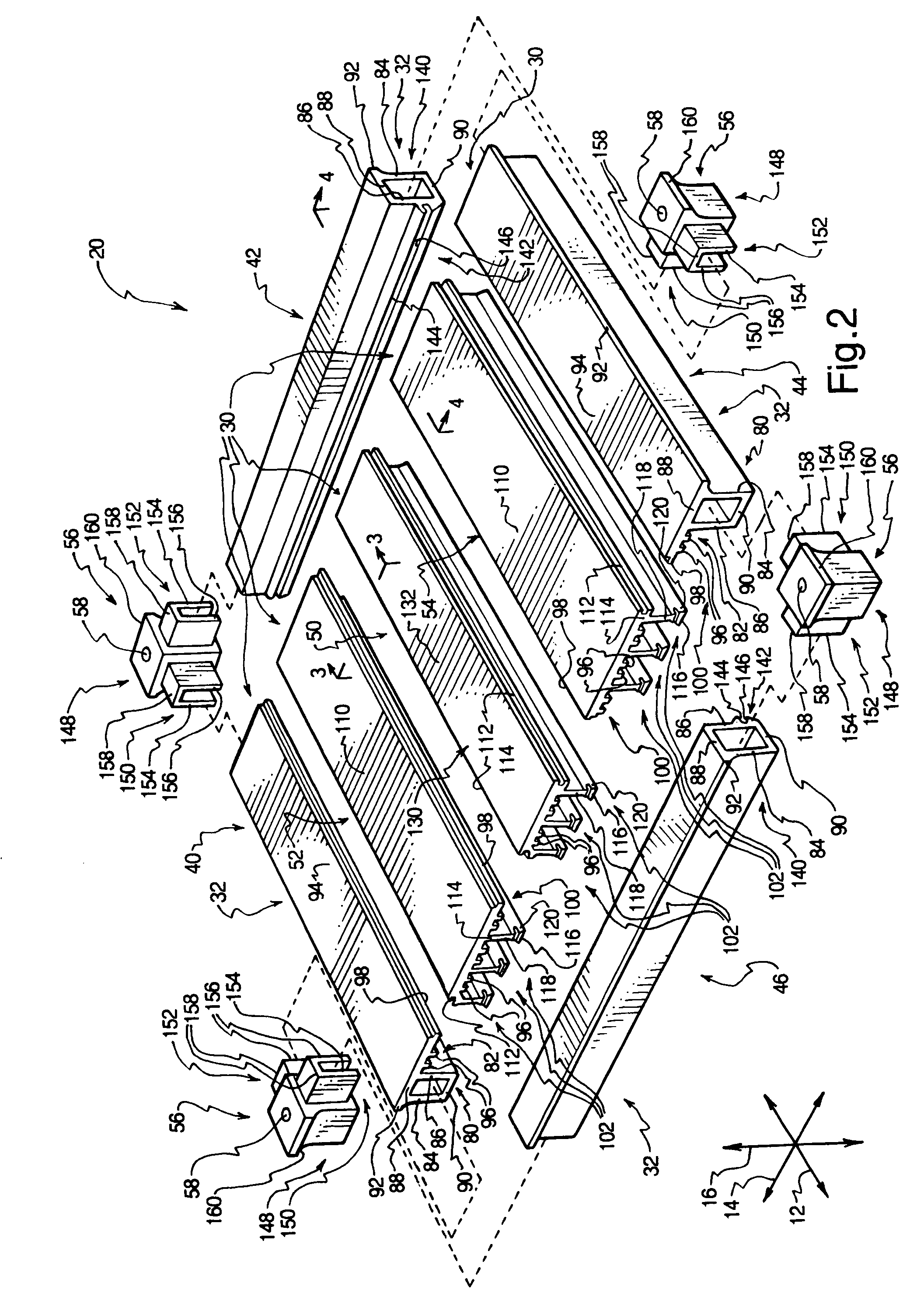
[0020]The majority of the panel is formed of extruded aluminum. The corner members may be cast from aluminum or steel. Each of the first and second edge members has a frame portion and a top surface portion. The frame portions each have an exterior web, an interior web, a top web, and a bottom web, so that each frame portion is configured generally as a box beam. Each frame portion may have a lip that extends outward. Each top surface portion has a horizontal plate that provides a portion of the top surface. The top surface portion also has a plurality of support spars that run longitudinally underneath the horizontal plate to enhance the bending resistance of the top surface portion. Additionally, each top surface portion of the first and second edge members has an attachment feature, which may take the form of a tongue that extends in the lateral direction.
[0026]As mentioned previously, the ends of the support ribs are pressed into engagement with the opposing ledges of the second and fourth edge members. The top ledges may each have an inward bevel and an outward bevel; the outward bevel facilitates insertion of the tab between the top and bottom ledges. The tab is defined by a slot formed in the end of the support rib. The tab is compressed between the top and bottom ledges. The interaction of the tab with the top and bottom ledges serves to reduce bowing of the top surface by aligning the support ribs with each other.
[0032]Furthermore, panels may easily be constructed at different sizes. For example, the intermediate members may be removed, or intermediate members may be added, to alter the lateral dimension of the panel. The second and fourth edge members are then simply lengthened or shortened accordingly. Alternatively, the first and second edge members, the intermediate members, and the center member may all be lengthened or shortened to alter the longitudinal dimension of the panel.
[0034]Through the use of the raised access floor and related methods presented herein, the strength-to-weight ratio, ease of use, and ease of installation of raised access floors may be greatly enhanced. These and other features and advantages of the present invention will become more fully apparent from the following description and appended claims, or may be learned by the practice of the invention as set forth hereinafter.

Problems solved by technology

Known raised access floors are limited in a number of respects.
For example, many raised access floors have comparatively low limitations regarding how much weight can be disposed over each panel.
Thus, relatively heavy equipment cannot be stored without using a heavy duty panel.
Heavy duty panels may be formed of die cast steel or the like, and are typically quite heavy.
Consequently, they are difficult to lift for removal or replacement, and thus impede access to the space underneath the raised access floor.
Some heavy duty panels are still unable to provide a sufficient load bearing capacity without exceeding OSHA standards for weights to be lifted manually.
Furthermore, many known panels for raised access floors are subject to brittle failure.
Such panels may show little strain until failure; thus, failure is catastrophic and occurs without warning.
Brittleness also provides a panel with a comparatively low toughness, or impact strength.
Thus, if a relatively heavy object is dropped onto the panel, breakage or weakening of the panel may result.
Furthermore, many known panels can only be produced in one size and shape.
Use of die casting or similar manufacturing methods provides a shape that cannot easily be modified without compromising the structural integrity of the shape.
Consequently, panels of odd sizes or panels with openings to provide wire or conduit passage, or the like, cannot easily be made, and, if cut from an existing cast panel, may not be sturdy enough for use in the environment.
Yet further, many known panels require enormous fixed costs to produce.
The die cannot readily be modified; hence, any alterations to the design of the panel will likely require a capital expenditure of the same magnitude.
This is because some panels do not have sufficient edge strength to prevent deformation at the junctures between the panels.
Consequently, each panel edge must be supported by a beam, or “stringer.” This also raises the cost and installation difficulty of the raised access floor, and severely impedes access to the space underneath the raised access floor because the framework is not removable.
This may make replacement or installation of certain types of equipment impossible underneath the raised access floor.
Moreover, some raised access floor panel designs have multiple parts that are not well-assembled.
In some instances, the raised access floor panel may be loaded in such a manner that assembled parts will tend to loosen over time, thereby compromising the design of the panel.
In other instances, attachment of parts of the panel is excessively reliant upon relatively labor intensive and / or unpredictable attachment methods such as welding.
Unfortunately, such covers may disrupt the panel's ability to serve as a grounding member to dissipate undesirable electric potential, such as static electricity.

Method used


Image

  • Raised access floor
  • Raised access floor
  • Raised access floor

Examples


Embodiment Construction

[0042]The presently preferred embodiments of the present invention will be best understood by reference to the drawings, wherein like parts are designated by like numerals throughout. It will be readily understood that the components of the present invention, as generally described and illustrated in the figures herein, could be arranged and designed in a wide variety of different configurations. Thus, the following more detailed description of the embodiments of the apparatus, system, and method of the present invention, as represented in FIGS. 1 through 6, is not intended to limit the scope of the invention, as claimed, but is merely representative of presently preferred embodiments of the invention.

[0043]For this application, the phrases “connected to,”“coupled to,” and “in communication with” refer to any form of interaction between two or more entities, including mechanical, electrical, magnetic, electromagnetic, and thermal interaction. The phrase “attached to” refers to a for...


PUM


Abstract

A raised access floor has panels suspended by pedestals. Each panel may have a top surface and a frame extending around the top surface. Each panel may have extruded aluminum components including four edge members, two intermediate members, and a center member. Each edge member may have a frame portion with a box beam configuration. The frame portions can be press-fitted with corner members to provide the frame. Two edge members, the intermediate members, and the center member may have top surface portions coupled together to form the top surface. The top surface may be supported by support ribs with enlarged bottom ends that resist bending. The ends of the support ribs are press-fitted against the frame. Components may be modified or removed to alter the panel geometry. A cover plate may be used to cover the top surface. The cover plate and / or top surface may be continuous or perforated.

Description

RELATED APPLICATIONS[0001]This application claims the benefit of U.S. Provisional Application No. 60 / 378,613 filed May 7, 2002 and entitled EXTRUDED ALUMINUM RAISED ACCESS FLOOR, which is incorporated herein by reference.BACKGROUND OF THE INVENTION[0002]1. Field of the Invention[0003]The present invention relates to flooring systems and methods. More specifically, the present invention relates to a raised access floor having removable panels with a high strength-to-weight ratio.[0004]2. Description of Related Art[0005]There are a wide variety of environments in which it may be desirable to store items such as fluid conduits, electrical wiring, machinery, or the like underneath a floor. Hence, many offices and manufacturing facilities use a dual flooring system, in which a raised access floor is suspended above a support surface. The raised access floor may have a pattern of removable tiles or panels that permit relatively easy access to the items between the support surface and the ...

Claims


Application Information

Patent Timeline
IPC IPC(8): E04B5/00E04B1/00
CPCE04F15/02452E04F15/02458
Inventor SPRANSY, PETER J.KUGATH, DON A.BUSHMAN, RONALD H.
Owner AIRTEX MFG LLLP
Learn More