Method and equipment for inspecting reinforced concrete pipe

a technology of inspection apparatus and reinforced concrete, which is applied in the direction of fluid pressure measurement by mechanical elements, vibration measurement in solids, fluid tightness measurement, etc., can solve the problem of inability to detect the progression level of deterioration in an appropriate and quantitative manner, cave-in and water leakage, etc. problem, to prevent the degradation of the accuracy of the tes

Inactive Publication Date: 2008-04-22
SEKISUI CHEM CO LTD
View PDF24 Cites 41 Cited by
  • Summary
  • Abstract
  • Description
  • Claims
  • Application Information

AI Technical Summary

Benefits of technology

[0011]According to the inspection method of the present invention, since the progression level of the deterioration of the component segment in the area to be inspected is classified and the portion to be inspected in detail is selected, the inspection operation time can be reduced. Further, the progression level of the deterioration in the portion to be inspected in detail can be evaluated based on the strength of the pipe in a quantitative manner.
[0025]As described above, by controlling the configuration of the receiver, receiving failure of the impact elastic waves (propagation waves) due to a contact failure between the receiver and the pipe inner surface caused from adhered layers, decayed layers on the inner surface layer of the reinforced concrete pipe constituting the sewage conduit, irrigation conduit or the like, or unevenness of the surface due to exposed reinforcing bars caused from abrasion, can be eliminated. Accordingly, the accuracy of the test can be prevented from degrading.

Problems solved by technology

In sewage and irrigation conduits built using reinforced concrete pipes, due to corrosion, abrasion and breakage caused from aging of concrete pipes, problems such as cave-in and water leakage have been increasing.
However, in the above-mentioned technique, only visible deterioration can be detected; accordingly, deterioration on the periphery and inside of the pipe cannot be detected.
Additionally, it is impossible to detect the progression level of deterioration in an appropriate and quantitative manner, and it is necessary to take out a large amount of cores to collect quantitative data.
Therefore, there arise such problems that the strength of the sewage or irrigation conduit is reduced, and significant manpower is required.
However, these systems are not satisfactory in workability.
When these systems are applied to the inspection of a structure extending over a long distance such as sewage and irrigation conduits, it takes a considerably long time for the inspection.

Method used


Image

  • Method and equipment for inspecting reinforced concrete pipe
  • Method and equipment for inspecting reinforced concrete pipe
  • Method and equipment for inspecting reinforced concrete pipe

Examples


embodiment 1

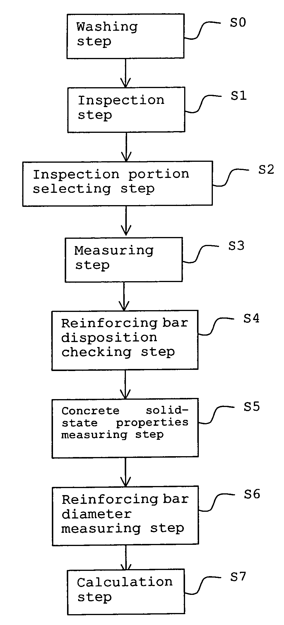
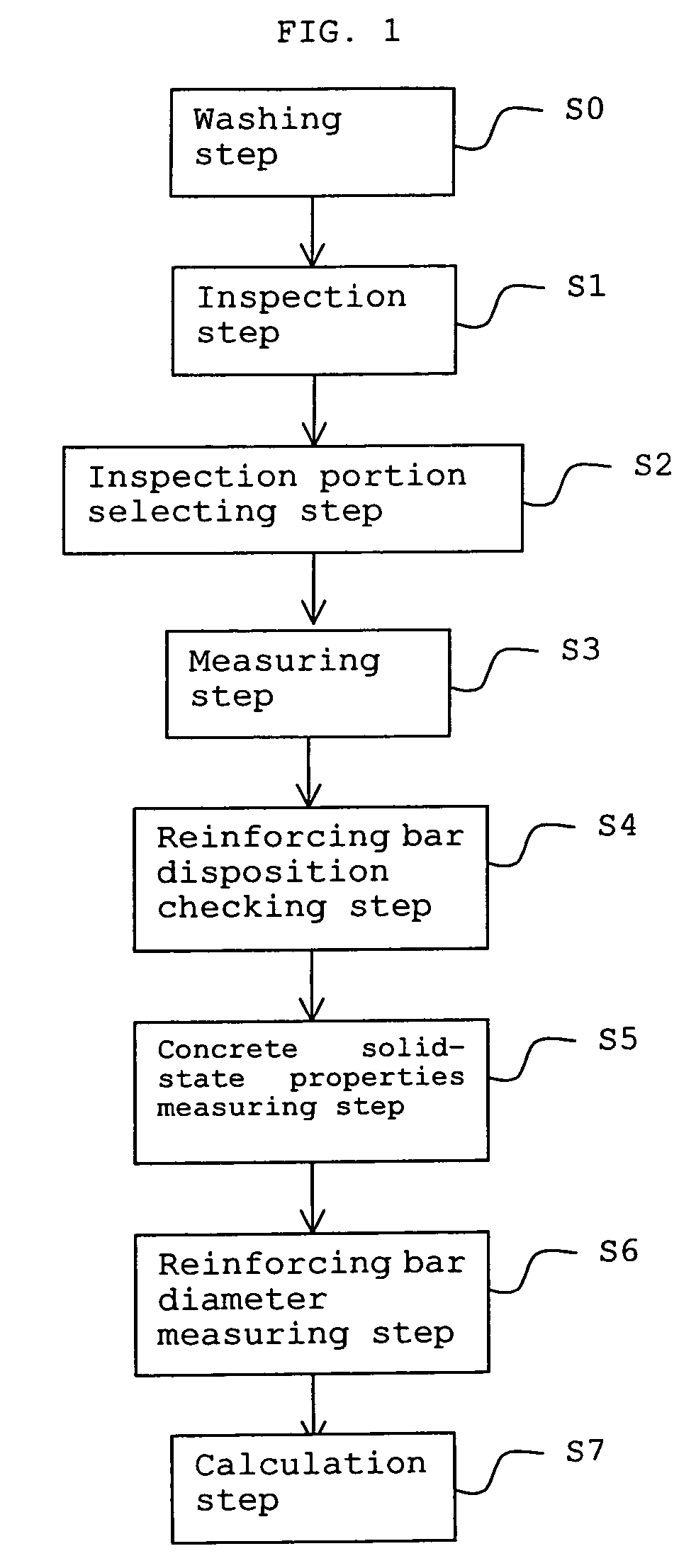
[0062]An embodiment of an inspection method according to the present invention will be described step by step with reference to FIG. 1.

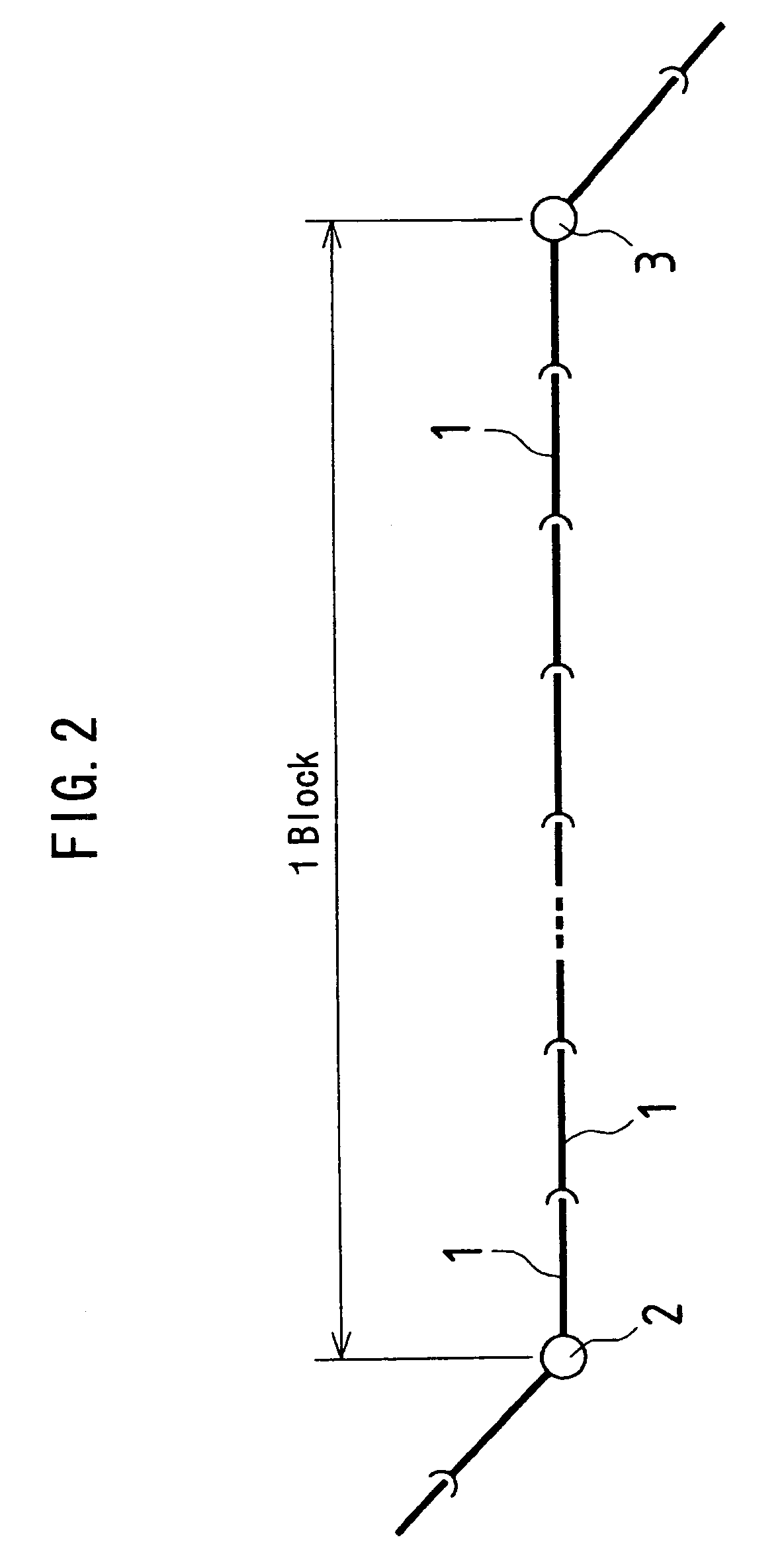
[0063]In this embodiment, as shown in FIG. 2, assuming that the segment from a manhole 2 to a manhole 3 is one block, tests, measurements and the like, which will be described later, are carried out on each of the reinforced concrete pipe 1 (Hume pipe) constituting the one block.

[0064][Washing Step S0]

[0065]When a large amount of extraneous matter remains on the inner surface of the pipe to be inspected, defects are prevented from being detected. The extraneous matter is to be removed by means of cutting using a cutting machine or a water jet washing.

[0066][Inspection step S1]

[0067]The following appearance test and impact elastic wave test are carried out.

[0068]

[0069]Corrosion abrasion, cracks, breakage, leakage of water or the like, which are recognizable on the inner surface of the pipe, are checked. As for the inspection method, when the diameter ...

example 1

[0112]A specific example of the present invention will be described.

[0113][Preparation of Sample]

[0114]The following samples of a product (inside diameter 400 mm) manufactured by Nippon Hume Corporation conforming to JIS A 5303 Type A-2 was prepared.

[0115]Sample T11: perfectly sound product

[0116]Sample T12: item introduced with water leak crack (deterioration progress level maximum)

[0117]Sample T13: item of which a part (central area) of bottom portion in the pipe inner surface was corroded with 1% vitriolic acid by approximately 1 mm in thickness (refer to FIG. 6)

[0118][Measuring Device]

[0119]Hammer: Schmitt hammer NR (manufactured by Fuji Bussan Co., Ltd.)

[0120]Receiver: AS-5 GB (manufactured by KYOWA Instruments Co., Ltd.)

[0121]Recording unit: EDX1500A (with amplifier) (manufactured by KYOWA Instruments Co., Ltd.)

[0122][Disposition of Measuring Device]

[0123]Disposition shown in FIG. 7 was employed.

[0124][Analysis Resonant Frequency]

[0125]The data of the propagated elastic wave, w...

embodiment 2

[0127]Another embodiment of the present invention will be described.

[0128]An injecting device and receiver used in the impact elastic wave test will be described first.

[0129]As for the injecting device, a hammering tool such as a hammer, a steel ball or an impulse hammer is available. In the impact elastic wave test, since it is preferred to carry out the hammering with the same force on a constant basis, for example, a method, in which the steel ball or the like is released with a specific force using a Schmitt hammer or spring; or a method, in which the steel ball or the like is dropped from a specific height, is employed. Further, a method, in which the hammering force of the impulse hammer is measured beforehand to take the influence of the hammering force into consideration during the data analysis, may be employed.

[0130]As for the receiver, an acceleration sensor, an AE sensor and vibration sensor or the like is available.

[0131]As for the setting method of the receiver, the re...


PUM

PropertyMeasurementUnit
resonant frequencyaaaaaaaaaa
areaaaaaaaaaaa

Abstract

Deterioration of reinforced concrete pipes is checked and the deterioration progress level is classified. Based on the inspection result, a portion to be inspected in detail in an inspection area is selected. With respect to the selected portion to be inspected in detail, the pipe thickness and the diameter of reinforcing bars are measured and the location of reinforcing bars in the portion to be inspected in detail are checked. Using the data of the thickness of a pipe, the diameter of the reinforcing bar and disposition of the reinforcing bars, structural analysis is carried out and the strength of the reinforced concrete pipe is calculated. The calculation result is used as information for evaluating the deterioration state of the reinforced concrete pipe.

Description

TECHNICAL FIELD[0001]The present invention relates to an inspection method and an inspection apparatus for inspecting the deterioration state of reinforced concrete pipes.BACKGROUND ART[0002]Conventionally, in a sewage conduit and irrigation conduit, many reinforced concrete pipes (Hume pipe) are used.[0003]In sewage and irrigation conduits built using reinforced concrete pipes, due to corrosion, abrasion and breakage caused from aging of concrete pipes, problems such as cave-in and water leakage have been increasing. Therefore, appropriate repair and renewal thereof based on appropriate diagnosis of the deterioration and the inspection result thereof are required.[0004]In the diagnosis and inspection of the sewage and irrigation conduits, generally, in order to determine the order and construction method of repair and renewal work, it is required to classify the progression level of deterioration in a component segment constituting the drainage basin to be inspected, and it is nece...

Claims


Application Information

Patent Timeline
Patent Type & Authority Patents(United States)
IPC IPC(8): G01N29/34G01M99/00G01M3/00G01M3/24G01N29/04G01N29/42G01N29/46
CPCG01M3/005G01M3/246G01N29/045G01N29/42G01N29/46G01N33/383F16L2101/30G01N2291/014G01N2291/0232G01N2291/2636G01N29/12G01N21/88G01M7/08G01B17/02
Inventor NOZAKI, YOSHIHARUMINAGI, TAKUSHI
Owner SEKISUI CHEM CO LTD
Why Eureka
Try Eureka