Switching control circuit having off-time modulation to improve efficiency of primary-side controlled power supply

a technology of switching control circuit and off-time modulation, which is applied in the direction of electric variable regulation, process and machine control, instruments, etc., can solve the problems that the prior art cannot meet the standard of accurate output voltage and the power consumption at light load conditions is significantly high, so as to save power consumption and reduce power consumption under light load conditions

Active Publication Date: 2008-04-22
FAIRCHILD SEMICON CORP
View PDF22 Cites 154 Cited by
  • Summary
  • Abstract
  • Description
  • Claims
  • Application Information

AI Technical Summary

Benefits of technology

[0005]A switching control circuit for a primary-side controlled power supply of the present invention comprises a switch for switching a transformer. A switching signal controls the switch for regulating the output voltage of the power supply. A controller is coupled to the transformer to generate a voltage-feedback signal by multi-sampling a voltage signal and a discharge time of the transformer during the off-time of the switching signal. A first operational amplifier and a first reference voltage develop a voltage-loop error amplifier to amplify the voltage-feedback signal and generate a control signal. The controller therefore generates the switching signal in response to the control signal. The controller comprises a voltage-waveform detector for multi-sampling the voltage signal and a discharge-time signal of the transformer to produce the voltage-feedback signal. The voltage-waveform detector is connected to an auxiliary winding of the transformer via a voltage divider. The discharge-time signal represents the discharge time of the transformer and stands for the discharge time of a secondary-side switching current. A PWM circuit controls the pulse width of the switching signal in response to the control signal. The output voltage is thus precisely regulated. An off-time modulator is developed to save the power consumption, in which a discharge-current signal and a standby signal are generated in response to the control signal and an under-voltage signal. The under-voltage signal indicates a low supply voltage of the controller. An oscillator is coupled to the discharge-current signal and the standby signal to generate a pulse signal for determining the off-time of the switching signal. The switching signal has a minimum switching frequency to switch the transformer for multi-sampling the voltage signal. The off-time of the switching signal is increased and the switching frequency is decreased in response to the decrease of the load and therefore the power consumption under light load condition is reduced.

Problems solved by technology

However, foregoing prior art cannot meet the standard of accurate output voltage.
Further, in such a design, the power consumption at light load condition is significantly high.

Method used


Image

  • Switching control circuit having off-time modulation to improve efficiency of primary-side controlled power supply
  • Switching control circuit having off-time modulation to improve efficiency of primary-side controlled power supply
  • Switching control circuit having off-time modulation to improve efficiency of primary-side controlled power supply

Examples


Embodiment Construction

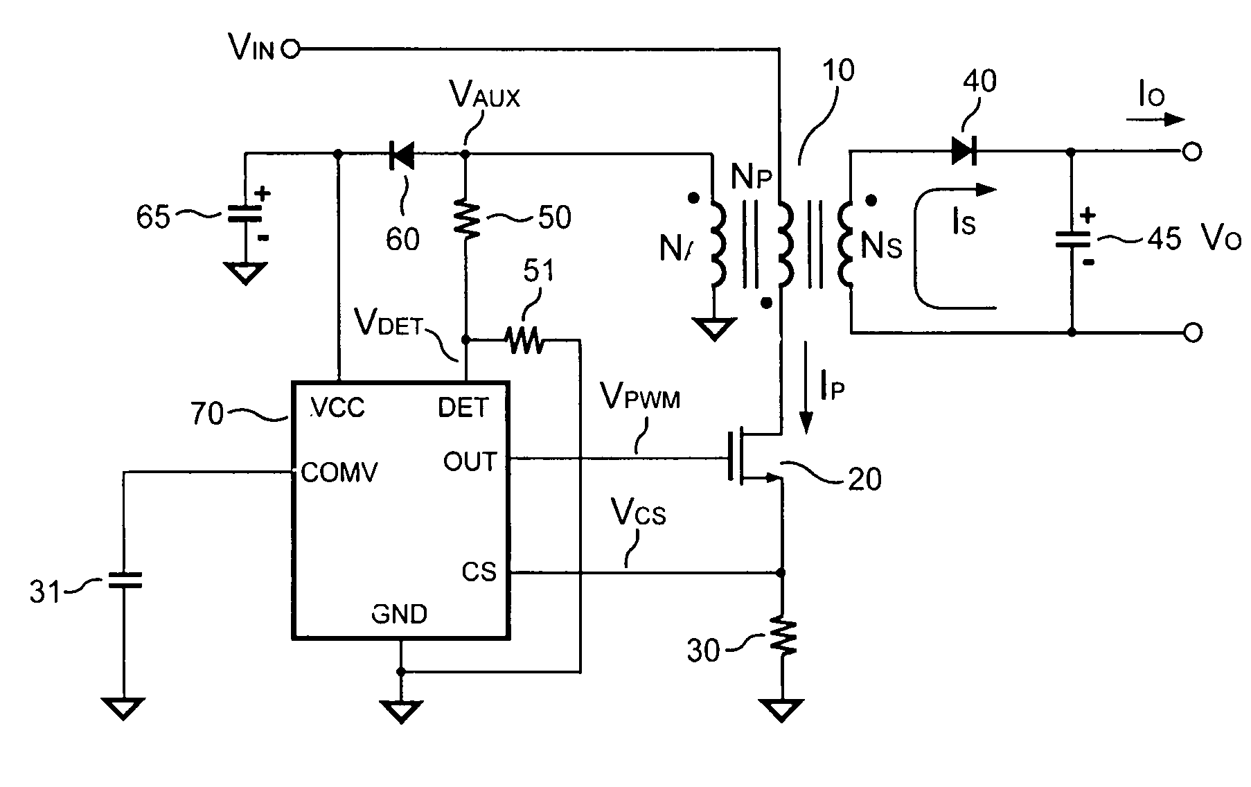
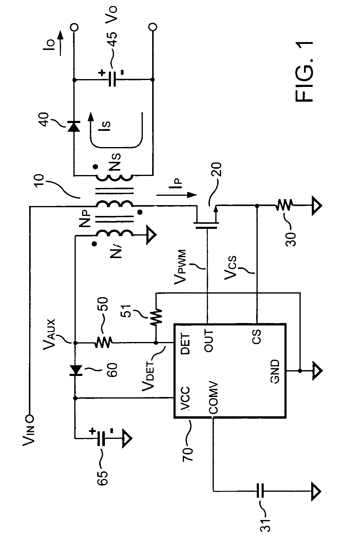
[0017]FIG. 1 shows a power supply. The power supply includes a transformer 10 comprising an auxiliary winding NA, a primary winding NP, and a secondary winding NS. The primary winding NP is coupled to an input voltage VIN of the power supply. In order to regulate an output voltage VO and / or an output current IO of the power supply, a switching control circuit includes a switching signal VPWM to control a switch, such as a transistor 20. A controller 70 generates the switching signal VPWM.

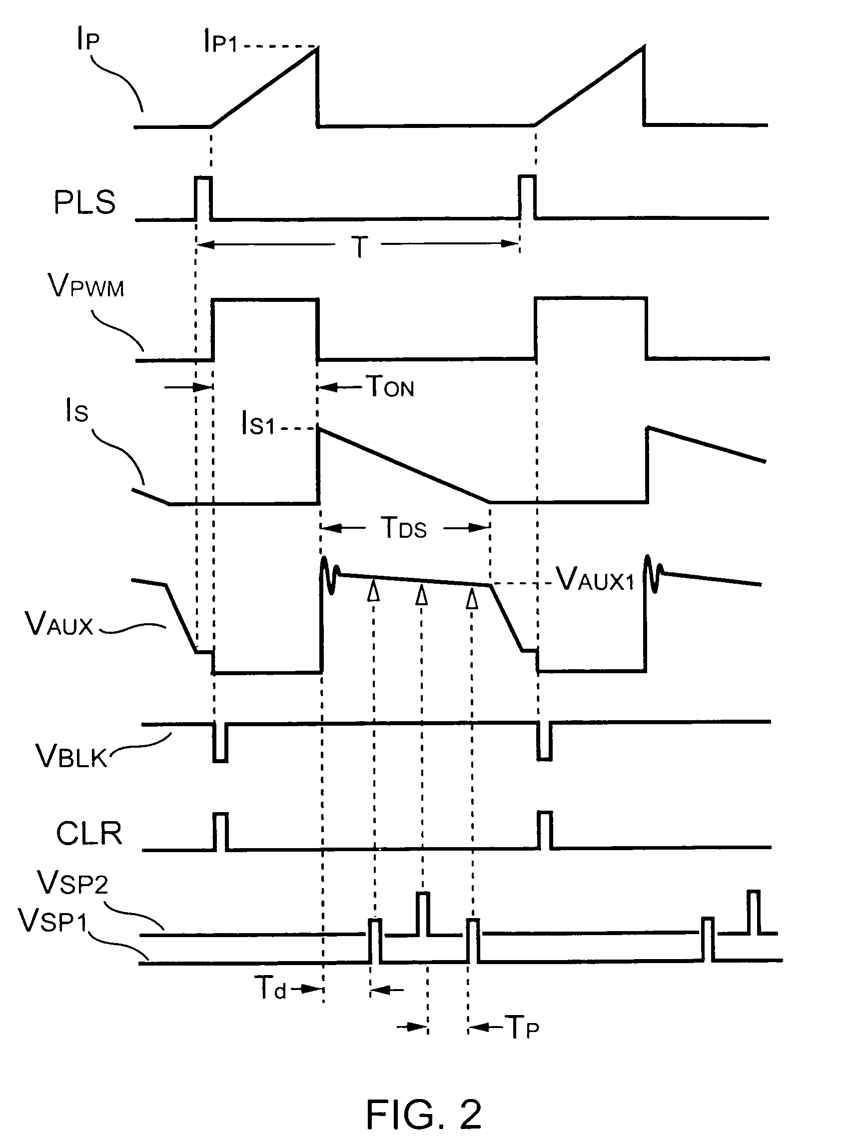
[0018]FIG. 2 shows various signal waveforms of the power supply in FIG. 1. As the switching signal VPWM is logic-high, a primary-side switching current IP will be generated accordingly. A primary-side switching peak current IP1 can be given by,

[0019]IP1=VINLP×TON(1)

[0020]where LP is the inductance of the primary winding NP of the transformer 10; TON is an on-time of the switching signal VPWM.

[0021]Once the switching signal VPWM is logic-low, the energy stored in the transformer 10 will be transferre...


PUM


Abstract

A voltage-waveform detector produces a voltage-feedback signal and a discharge-time signal by multi-sampling a voltage signal of a transformer. The discharge-time signal represents a discharge time of a secondary-side switching current. A voltage-loop error amplifier amplifies the voltage-feedback signal and generates a control signal. An off-time modulator correspondingly generates a discharge-current signal and a standby signal in response to the control signal and an under-voltage signal. The under-voltage signal indicates a low supply voltage of the controller. An oscillator produces a pulse signal in response to the discharge-current signal. The pulse signal determines the off-time of the switching signal. A PWM circuit generates the switching signal in response to the pulse signal and the standby signal. The standby signal further controls the off-time of the switching signal and maintains a minimum switching frequency. The switching signal is used for regulating the output of the power supply.

Description

BACKGROUND OF THE INVENTION[0001]1. Field of the Invention[0002]The present invention relates to a control circuit for a power supply, and more specifically, to a switching control circuit for switching mode power supplies.[0003]2. Description of Related Art[0004]Various power supplies have been widely used to provide regulated voltage. For the sake of safety, an off-line power supply is used to provide galvanic isolation between its primary side and secondary side. An optical-coupler and a secondary-side regulator are usually needed for regulating the output voltage of the off-line power supply. In order to reduce the device count and do without the secondary feedback circuit, a primary-side control technique has been disclosed in U.S. Pat. No. 4,302,803 “Rectifier-Converter Power Supply with Multi-Channel Flyback Inverter,” issued to Randolph D. W. Shelly, on Nov. 24, 1981. However, foregoing prior art cannot meet the standard of accurate output voltage. Further, in such a design,...

Claims


Application Information

Patent Timeline
Patent Type & Authority Patents(United States)
IPC IPC(8): H02M3/335
CPCH02M3/33507H02M2001/0032Y02B70/16H02M1/0032Y02B70/10
Inventor YANG, TA-YUNGHUNG, GUO-KIANGLIN, JENN-YU G.LI, CHUH-CHINGTSAO, FENG CHENG
Owner FAIRCHILD SEMICON CORP
Why Eureka
Try Eureka