Microcircuit cooling for vanes

a micro-circuit and vanes technology, applied in the direction of machines/engines, foundry patterns, machine/engines, etc., can solve the problems of frequent clogging of cooling film exit holes on such components, severe reduction of cooling effectiveness, and high thermal loads on the suction side of turbine vanes. , to achieve the effect of increasing the performance of the cooling micro-circui

Active Publication Date: 2008-04-29
RTX CORP
View PDF3 Cites 54 Cited by
  • Summary
  • Abstract
  • Description
  • Claims
  • Application Information

AI Technical Summary

Benefits of technology

[0006]In accordance with the present invention, a cooling microcircuit is provided which addresses high thermal loads on the suction side of the airfoil portion of turbine engine components, particularly turbine vanes, and which keeps the last row of cooling holes ahead of the gage or throat point which increases the performance of the cooling microcircuit.
[0007]In accordance with the present invention, a cooling microcircuit is provided which prevents slot exit plugging.

Problems solved by technology

Turbine vanes in particular are subjected to high thermal loads on the suction side of the airfoil portion.
In addition to thermal load problems, cooling film exit holes on such components are frequently plugged by contaminants.
Such plugging can cause a severe reduction in cooling effectiveness since the flow of cooling fluid over the exterior surface of the suction side is reduced.

Method used


Image

  • Microcircuit cooling for vanes
  • Microcircuit cooling for vanes
  • Microcircuit cooling for vanes

Examples


Embodiment Construction

)

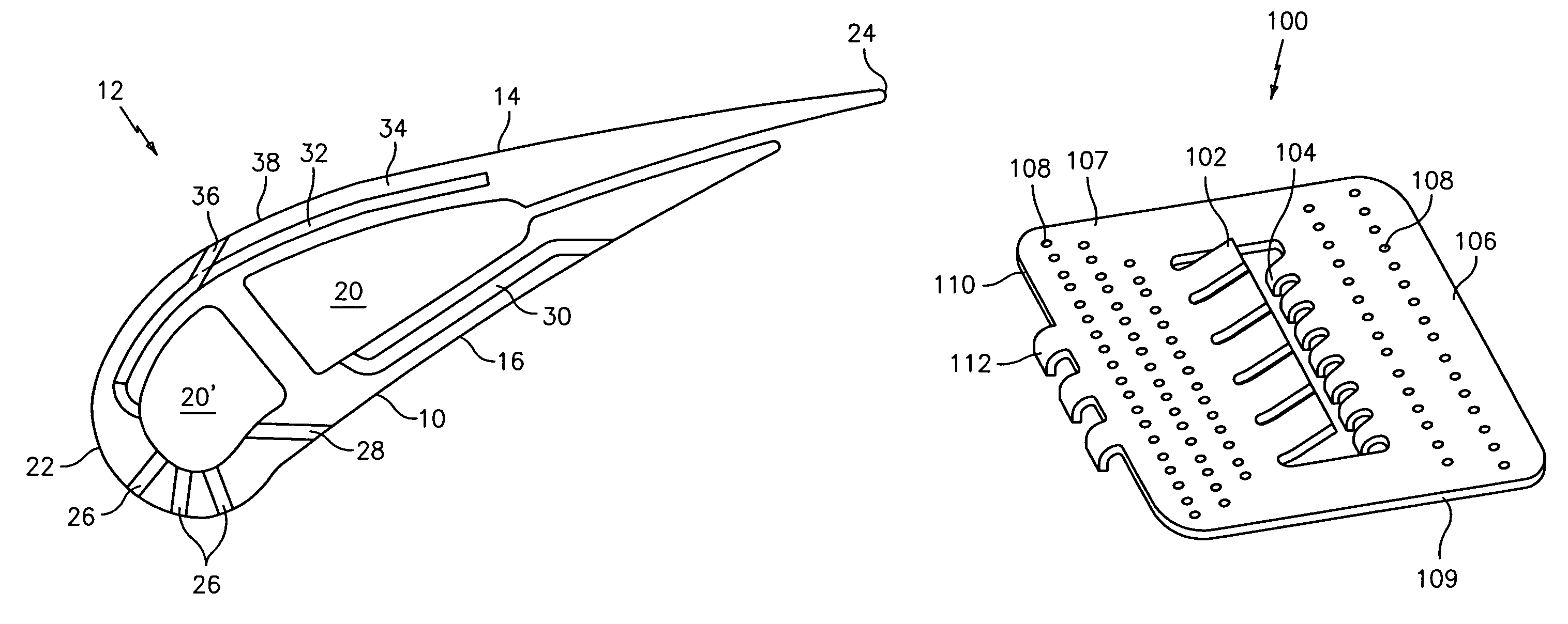
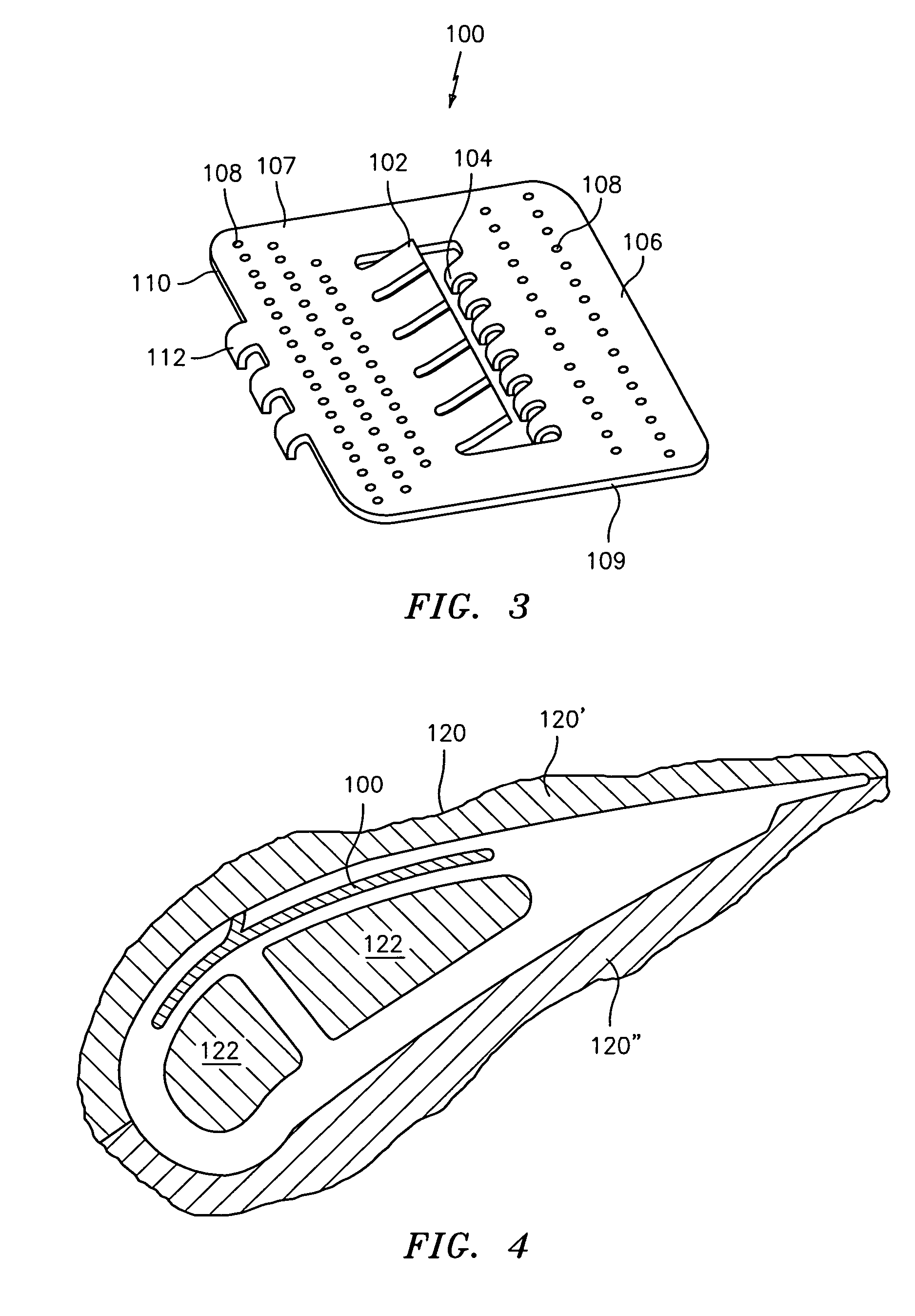
[0018]The present invention relates to an internal cooling microcircuit positioned within the airfoil portion of a turbine engine component such as a turbine vane.

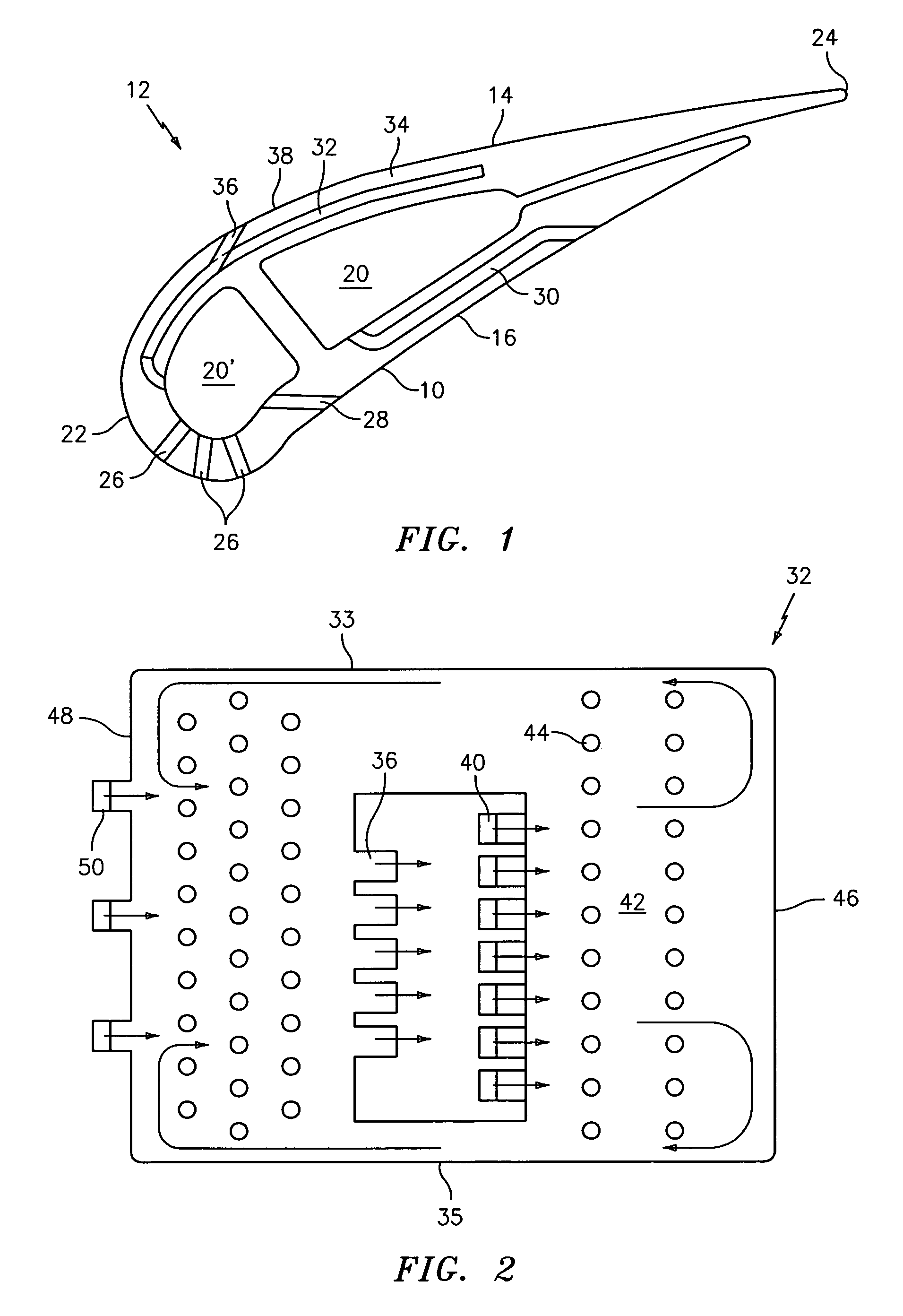
[0019]FIG. 1 illustrates an airfoil portion 10 of a turbine engine component 12 such as a turbine vane. The airfoil portion 10 has a suction side 14 and a pressure side 16. The airfoil portion 10 also may have one or more core elements 20 and 20′ through which cooling fluid may flow. Each core element 20 and 20′ may communicate with a source (not shown) of a cooling fluid such as engine bleed air. The airfoil portion 10 has a leading edge 22 and a trailing edge 24.

[0020]The airfoil portion 10 may have a number of passageways for cooling various portions of its exterior surface. For example, the airfoil portion 10 may have one or more leading edge cooling passageways 26 and 28 which are in fluid communication with the core element 20′. The airfoil portion 10 may also have a cooling passageway 30 for causing cooling fluid t...


PUM

PropertyMeasurementUnit
angleaaaaaaaaaa
refractoryaaaaaaaaaa
temperatureaaaaaaaaaa

Abstract

A turbine engine component has an airfoil portion with a suction side. The component includes a cooling microcircuit embedded within a wall structure forming the suction side. The cooling microcircuit has at least one cooling film hole positioned ahead of a gage point for creating a flow of cooling fluid over an exterior surface of the suction side which travels past the gage point. The cooling microcircuit is formed using refractory metal core technology. A method for forming the cooling microcircuit is described.

Description

BACKGROUND OF THE INVENTION[0001](1) Field of the Invention[0002]The present invention relates to a cooling microcircuit that addresses high thermal loads on the airfoil suction side in turbine engine components, such as turbine vanes.[0003](2) Prior Art[0004]Turbine engine components such, as turbine vanes, are operated in high temperature environments. To avoid structural defects in the components resulting from their exposure to high temperatures, it is necessary to provide cooling circuits within the components. Turbine vanes in particular are subjected to high thermal loads on the suction side of the airfoil portion.[0005]In addition to thermal load problems, cooling film exit holes on such components are frequently plugged by contaminants. Such plugging can cause a severe reduction in cooling effectiveness since the flow of cooling fluid over the exterior surface of the suction side is reduced.SUMMARY OF THE INVENTION[0006]In accordance with the present invention, a cooling mi...

Claims


Application Information

Patent Timeline
Patent Type & Authority Patents(United States)
IPC IPC(8): F01D5/08
CPCB22C9/06B22C9/108B22D29/002F01D5/186Y10T29/49341F05D2230/21F05D2260/202F05D2300/13F01D5/18F01D5/00
Inventor CUNHA, FRANKDAHMER, MATTHEW T.
Owner RTX CORP
Why Eureka
Try Eureka