
Catalysts

a catalyst and catalyst technology, applied in the field of catalysts, can solve the problems of contaminated wax products with ultra-fine cobalt rich particulates, and the synthesis catalyst of fischer-tropsch is susceptible to hydrothermal attack, and achieve the effect of reducing the catalyst precursor

Active Publication Date: 2008-04-29
SASOL TEKHNOLODZHI PROPRIEHJTEHRI LTD
View PDF21 Cites 46 Cited by
  • Summary
  • Abstract
  • Description
  • Claims
  • Application Information

AI Technical Summary

Benefits of technology

"The patent text describes a process for preparing a cobalt-based Fischer-Tropsch synthesis catalyst by introducing a soluble modifying component onto a pre-shaped catalyst support and reducing it to obtain a modified cobalt-based Fischer-Tropsch synthesis catalyst. This process allows for the production of a catalyst that does not require the addition of a modifying component after production of the pre-shaped support. The modified catalyst has improved stability and is less contaminated with ultra-fine particulate matter enriched in cobalt, resulting in a cleaner wax product. The process involves introducing a modifying component precursor onto the catalyst support and reducing it to obtain the modified catalyst. The invention also includes a Fischer-Tropsch catalyst produced by this process."

Problems solved by technology

The presence of this physically bonded layer contributes to insufficient anchoring of the Fischer-Tropsch synthesis active cobalt crystallites, and facilitates the eventual dislodging and washing out of cobalt rich ultra-fine particulate matter from the porous catalyst during extended Fischer-Tropsch synthesis in a three phase bubble column reactor.The Fischer-Tropsch synthesis catalyst is susceptible to hydrothermal attack that is inherent to realistic synthesis conditions, ie syngas conversions in excess of 50% at medium pressure operation where the synthesis gas is not unduly diluted.
A successful hydrothermal attack on the exposed (and unprotected) support material will result in contamination of the produced wax product with ultra-fine cobalt rich particulate matter.

Method used


Image

  • Catalysts
  • Catalysts

Examples


example 2

Preparation of Modified Catalyst Precursor B

[0044]A cobalt catalyst precursor was prepared in a similar manner to catalyst precursor A, and subsequently modified with silica, to obtain a modified catalyst precursor B. An impregnation method was used to achieve the modification. Thus, silicon, in the form of TEOS (tetra ethoxy silane, 2,5 kg) as precursor, was added to 20 L ethanol at 60° C. Ethanol was thus used as the impregnation solvent. 20 kg of catalyst precursor A of Example 1, was added to this solution, which was then kept at 50° C.-75° C. for 1 hour. Subsequently, the solvent was removed under vacuum at 0.03-0.2 bar(a), with a jacket temperature of the drier equipment of 95° C. The drying step was terminated after 2 hours, and the resultant dried impregnated support was loaded immediately into a fluidized bed calciner. The loading took about 1 to 2 minutes, and the temperature remained at its set point of about 75° C. The temperature of the fluidized bed was increased at a ...

example 3

Laboratory Slurry Phase Fischer-Tropsch Synthesis

[0045]Cobalt catalyst precursors (modified or unmodified) were reduced prior to Fischer-Tropsch synthesis in a tubular reactor at a hydrogen space velocity of 200 mln hydrogen / g catalyst / h and atmospheric pressure. The temperature was increased to 425° C. at 1° C. / min, after which isothermal conditions were maintained for 16 hours. Comparative Catalyst A was thus obtained from catalyst precursor A, while Catalyst B was thus obtained from modified catalyst precursor B.

[0046]Between 10 g and 30 g of the resultant reduced catalyst, ranging between 38 μm to 150 μm, was suspended in 300 ml molten wax and loaded in a CSTR with an internal volume of 500 ml. The feed gas consisted of hydrogen and carbon monoxide in a H2 / CO molar ratio from 1.5 / l to 2.3 / l. This reactor was electrically heated and sufficiently high stirrer speeds were employed so as to eliminate any gas-liquid mass transfer limitations. The feed flow was controlled by means of ...

example 4

Pilot Plant Fischer-Tropsch Synthesis Tests

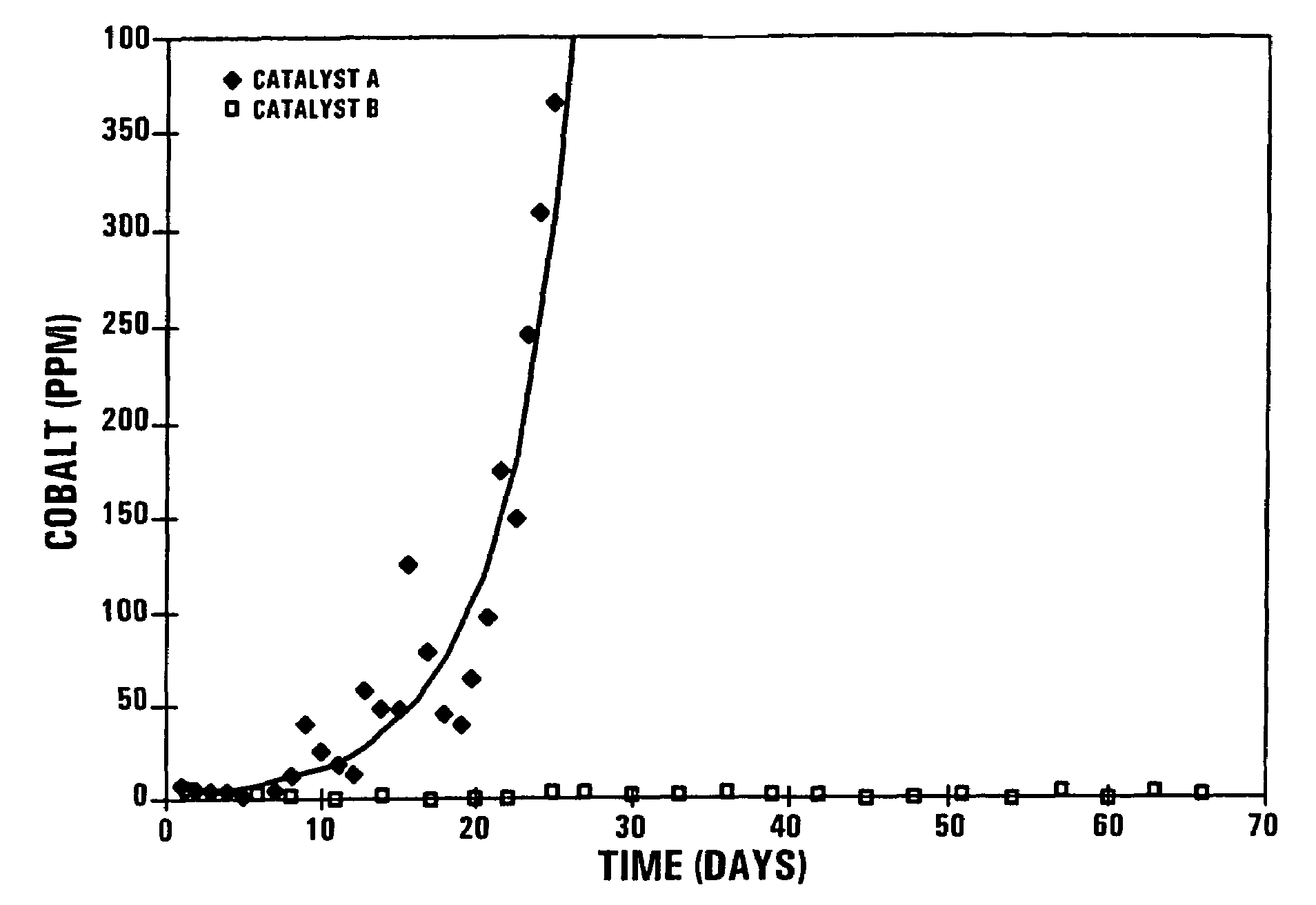
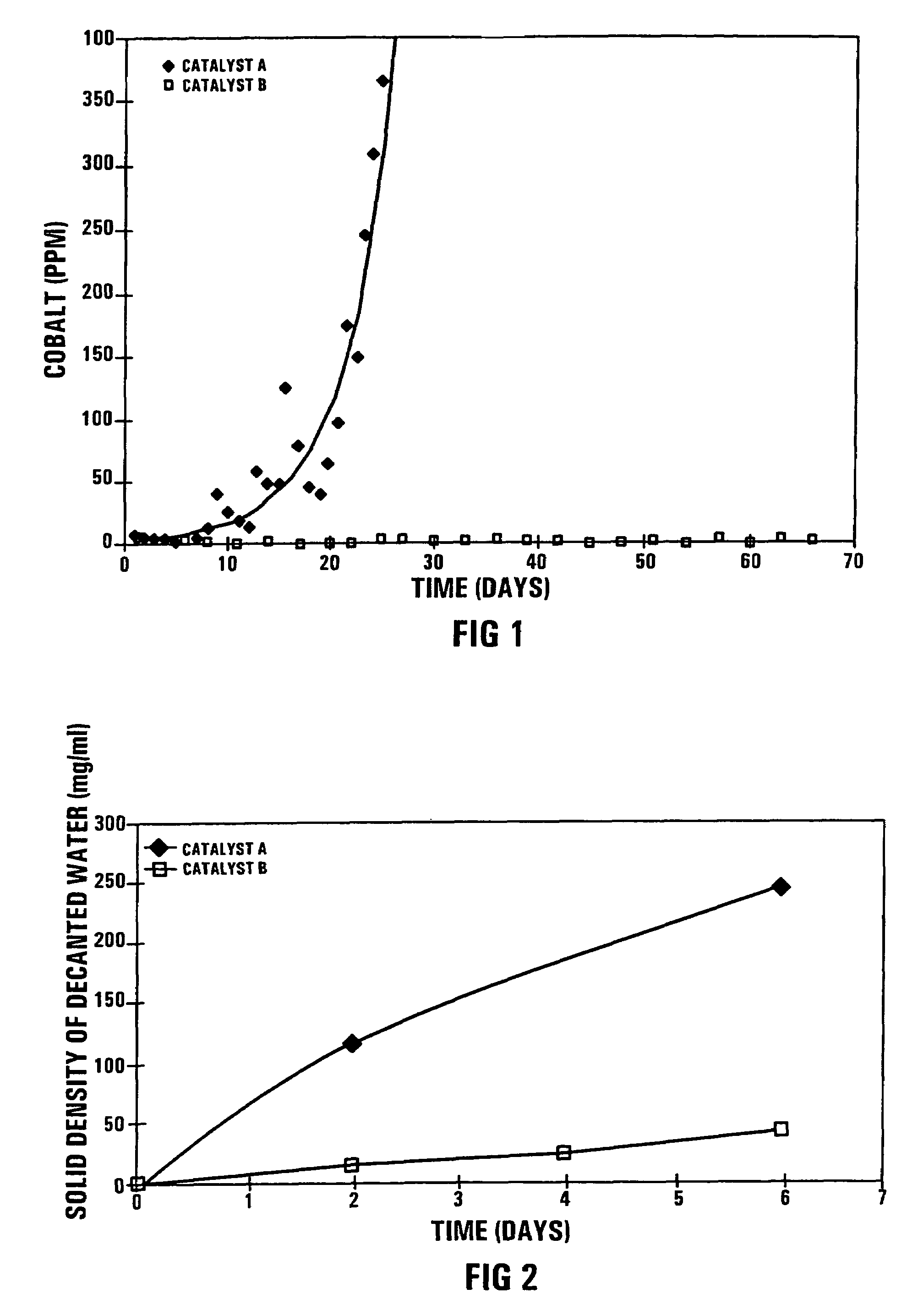
[0051]During a confidential Pilot Plant Fischer-Tropsch synthesis test run, using 5 kg of the catalyst A in a 11 m high bubble column reactor with an external recycle, the secondary filtered wax product turned grey after about 10 days on-line and the cobalt content increased to 350 mass ppm after 25 days on line, as shown in FIG. 1. The secondary filtered wax product is defined as the wax product produced in the Fischer-Tropsch synthesis test run and which has been subjected to a primary solids separation step, and thereafter to secondary ex-situ filtration through Whatmans 42 (trademark) filter paper.

[0052]The test run was performed under realistic Fischer-Tropsch synthesis conditions:

[0053]

Reactor temperature:230° C.Reactor pressure:20 Bar% (H2 + CO) conversion:50-80%Feed gas composition:H2:ca 50 vol %CO:ca 25 vol %Balance:Ar, N2, CH4 and or CO2

[0054]The pilot plant test run was repeated with Catalyst B, using an identical quantity of Cat...


PUM

PropertyMeasurementUnit
pore diameteraaaaaaaaaa

Abstract

A process for preparing a cobalt-based Fischer-Tropsch synthesis catalyst includes introducing a soluble modifying component precursor of the formula Mc(OR)x, where Mc is a modifying component selected from the group comprising Si, Ti, Cu, Zn, Zr, Mn, Ba, Ni, Na, K, Ca, Sn, Cr, Fe, Li, Tl, Sr, Ga, Sb, V, Hf, Th, Ce, Ge, U, Nb, Ta, W or La, R is an alkyl or acyl group, and x is an integer having a value of from 1 to 5, onto and / or into a cobalt-based Fischer-Tropsch synthesis catalyst precursor, which comprises a porous pre-shaped catalyst support supporting cobalt in an oxidized form. The resultant modified cobalt-based Fischer-Tropsch synthesis catalyst precursor is reduced to obtain a cobalt-based Fischer-Tropsch synthesis catalyst.

Description

[0001]This application claims the benefit of U.S. Provisional Application No. 60 / 565,468 filed Apr. 26, 2004 and incorporates the same by reference.[0002]THIS INVENTION relates to catalysts. It relates in particular to a process for preparing a cobalt-based Fischer-Tropsch synthesis catalyst, and to a Fischer-Tropsch synthesis catalyst when prepared by the process.[0003]When a Fischer-Tropsch synthesis catalyst that has been produced from a pre-shaped catalyst support, which is partially soluble in an acid or neutral aqueous solution, by means of aqueous slurry phase impregnation of cobalt as an active catalyst component onto the catalyst support, drying the impregnated support, calcining the dried impregnated support to obtain a catalyst precursor, and reducing the catalyst precursor to obtain a Fischer-Tropsch synthesis catalyst, is used for Fischer-Tropsch synthesis in a three-phase bubble column, contamination of the wax product produced during Fischer-Tropsch synthesis with ult...

Claims


Application Information

Patent Timeline
Patent Type & Authority Patents(United States)
IPC IPC(8): B01J21/00B01J20/00B01J23/40B01J23/58B01J23/60B01D37/02B01JB01J21/06B01J21/08B01J21/12B01J23/75B01J23/76B01J23/89B01J31/02B01J33/00B01J35/00B01J37/02B01J37/16B01J37/18C07C1/04C07C1/06C07C7/148C07C9/00C07C27/06C10G2/00C10G45/00C10G49/00
CPCB01J23/75B01J23/8913B01J31/0274C10G2/332B01J37/0209B01J21/12B01J23/76B01J33/00B01J37/0203B01J37/16B01J37/18B01J2231/641B01J2231/648B01J35/023B01J35/40B01J37/02
Inventor VAN BERGE, PETER JACOBUSBARRADAS, SEAN
Owner SASOL TEKHNOLODZHI PROPRIEHJTEHRI LTD
Learn More