
Liquid crystal display

a liquid crystal display and display technology, applied in the field of inplane switching, can solve the problems of narrow viewing angle, insufficient improvement of contrast, and reduced contrast, and achieve the effect of reducing the difference in absolute value and good contras

Active Publication Date: 2008-04-29
NITTO DENKO CORP
View PDF9 Cites 16 Cited by
  • Summary
  • Abstract
  • Description
  • Claims
  • Application Information

AI Technical Summary

Benefits of technology

The invention is a liquid crystal display that uses an optical film made of a polarizing plate and a retardation film to improve the contrast ratio and viewing angle. The film is designed to reduce light leakage and color shifting while also compensating for reduced contrast in an oblique viewing angle. The technical effect of the invention is to provide a high-contrast liquid crystal display with a wide viewing angle and good color quality.

Problems solved by technology

In conventional in-plane switching type active matrix liquid crystal display, however, an almost perfect black viewing can be achieved in a direction normal to a panel, whereas in a case where the panel is viewed in a direction deviated from the direction normal to the panel, there has been remained a problem that unavoidable light leakage as a characteristic of a polarizing plate occurs in a direction deviated from the optical axis of the polarizing plates disposed on the top or bottom of a liquid crystal cell with the result that a viewing angle is narrowed and a contrast is reduced.
This technique is effective for a color shift, but cannot improve a contrast sufficiently.

Method used


Image

  • Liquid crystal display
  • Liquid crystal display
  • Liquid crystal display

Examples


example 1

(Retardation Films A1 and A2)

[0096]

[0097]Dissolved into 75 parts by weight of cyclohexanone were 5 pats by weight of a side chain type liquid crystal polymer expressed by the chemical formula 6 (wherein numerals each indicate a molar percentage of a monomer unit, and which is exhibited by a block polymer unit for convenience, and a weight average molecular weight was 5000); 20 parts by weight of a polymerizable liquid crystal showing a nematic liquid crystal phase (Paliocolor LC242, manufactured by BASF LTD.) and 3 parts by weight of a photoinitiator (IRGACURE 907 manufactured by Ciba Specialty Chemicals Co.) to polymerizable liquid crystal to thereby prepare a solution. The solution was coated on a stretched base film (ZEONOR film manufactured by Nippon Zeon Co., Ltd.) to thickness of 0.6 μm with a bar coater, the wet coat was dried at 100° C. for 10 min, the dry coat is illuminated with UV and cured to thereby obtain a homeotropic aligned liquid crystal layer. The homeotropic alig...

example 2

[0104](Retardation Film A1)

[0105]A homeotropic aligned liquid crystal layer was obtained in a similar way to that in Example 1 with the exception that in Example 1, coating was applied to thickness of 0.5 μm. The homeotropic aligned liquid crystal layer had in-plane retardation (Re) of almost zero and retardation in the thickness direction (Rth2) of −50 nm.

(Retardation Film B)

[0106]A stretched film was obtained in a similar way to that in Example 1 with the exception that in Example 1, a stretch ratio is changed to 1.28. The obtained stretched film had in-plane retardation (Re) of 255 nm and Nz coefficient of 0.54.

(Polarizing Plate Attached with a Retardation Film Thereon on the Viewing Side)

[0107]A polarizing plate-attached with a retardation film was obtained in a similar way to that in Example 1 with the exception that in Example 1, the retardation film A1 and retardation film B, both having been obtained above, are used. The polarizing plate attached with the retardation film th...

example 3

(Retardation Film A1)

[0111]A homeotropic aligned liquid crystal layer was obtained in a similar way to that in Example 1 with the exception that in Example 1, coating was applied to thickness of 0.7 μm. The homeotropic aligned liquid crystal layer had in-plane retardation (Re) of almost zero and retardation in the thickness direction (Rth2) of −70 nm.

(Retardation Film B)

[0112]A stretched film was obtained in a similar way to that in Example 1 with the exception that in Example 1, a stretch ratio is changed to 1.32. The obtained stretched film had in-plane retardation (Re) of 290 nm and Nz coefficient of 0.45.

(Polarizing Plate Attached with a Retardation Film Thereon on the Viewing Side)

[0113]A polarizing plate attached with a retardation film was obtained in a similar way to that in Example 1 with the exception that in Example 1, the retardation film A1 and retardation film B, both having been obtained above, are used. The polarizing plate attached with the retardation film thereon ...


PUM

PropertyMeasurementUnit
thicknessaaaaaaaaaa
thicknessaaaaaaaaaa
thicknessaaaaaaaaaa

Abstract

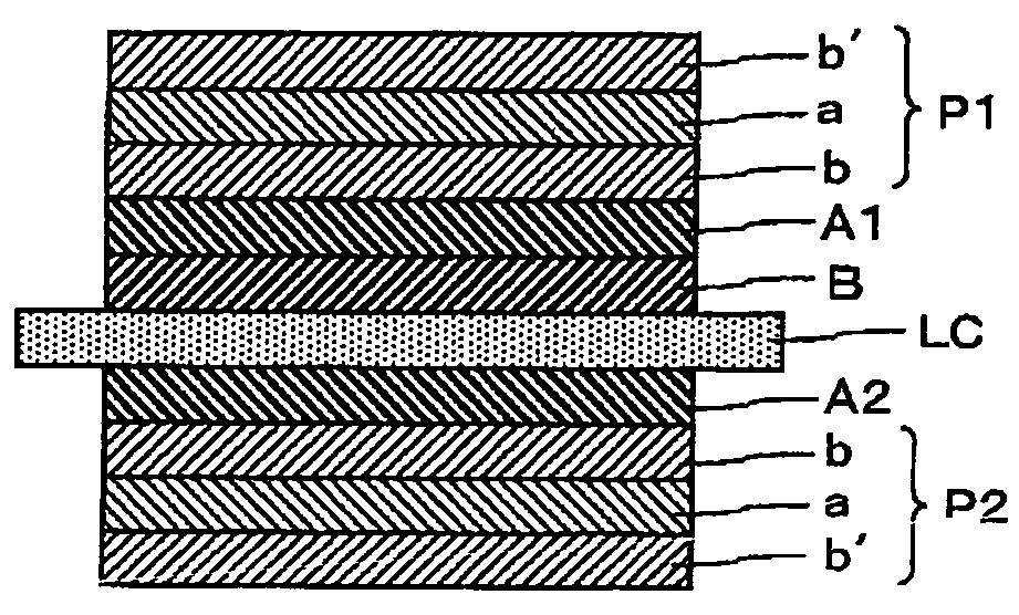
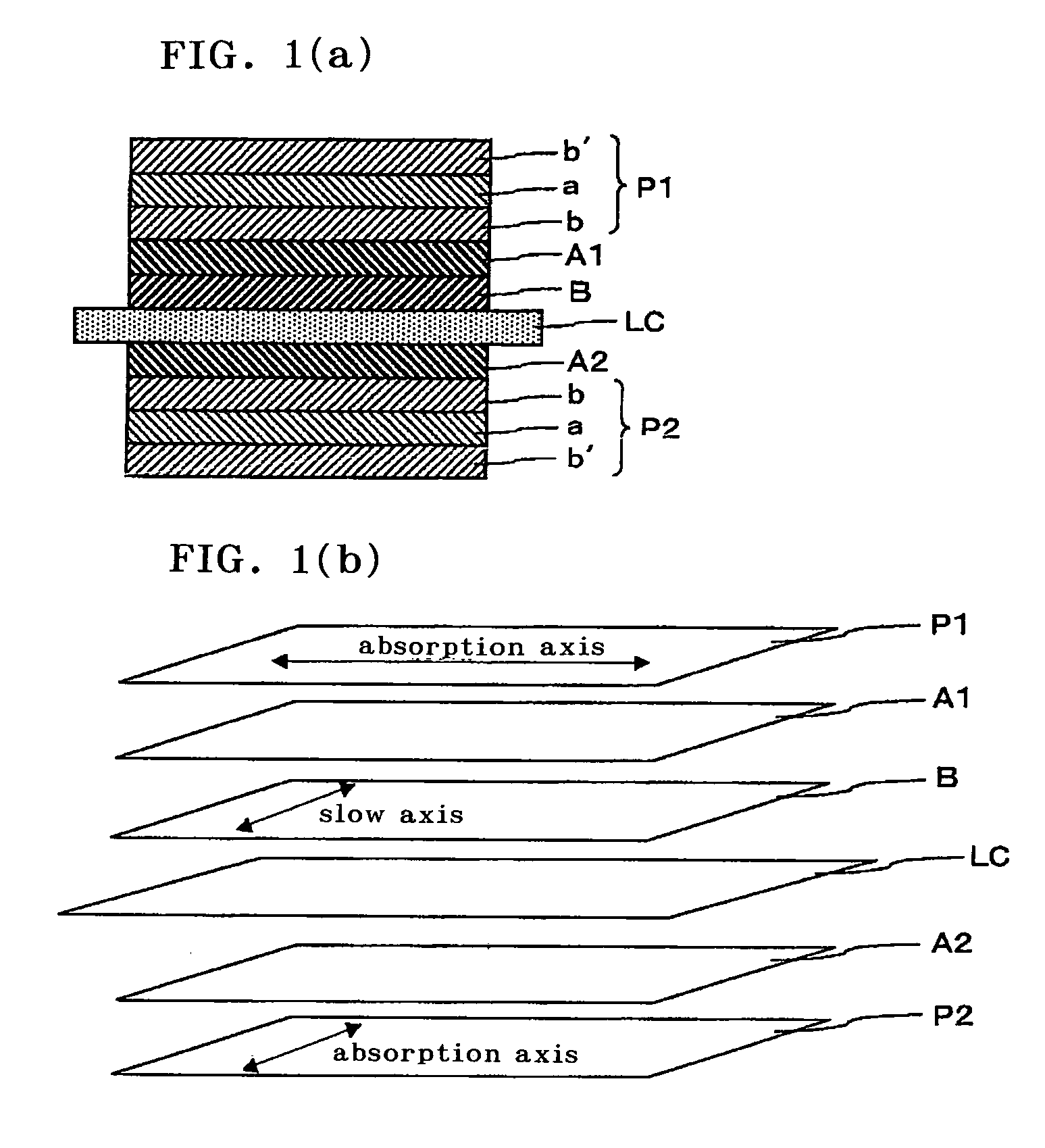
A liquid crystal display of the invention comprises an in-plane switching liquid crystal panel containing a liquid crystal layer whose alignment orientation changes according to an electric field in parallel with a surface of a substrate; a first polarizing plate and a second polarizing plate disposed sandwiching the liquid crystal panel therebetween; a first optical film inserted between the first polarizing plate and the liquid crystal panel; and a second optical film inserted between the second polarizing plate and the liquid crystal panel, wherein the first optical film includes: a retardation film A 1 having a relation of nz>nx>=ny; and a retardation film B having an in-plane retardation (Re) in the range of from 200 to 300 nm, a relation of nx>nz>ny and satisfying Nz coefficient in the range of 0.3<Nz<0.7, in which three-dimensional refractive indices are controlled; the second optical film includes a retardation film A 2 having a relation of nz>nx>=ny; and the slow axis of the retardation film B is in parallel with or perpendicular to the absorption axes of the first and second polarizing plates. The liquid crystal display has a high contrast ratio over a wide range.

Description

TECHNICAL FIELD[0001]This invention relates to an in-plane switching (IPS) type active matrix liquid crystal display.BACKGROUND ART[0002]An in-plane switching type liquid crystal display presents a pixel display in a way such that an electric field in parallel with a liquid crystal substrate is formed between pixel electrodes and a common electrode. The liquid crystal display of this type has an advantage that a wide viewing angle is obtained as compared with a TN mode type liquid crystal display in which a vertical electric field to a substrate is formed. In conventional in-plane switching type active matrix liquid crystal display, however, an almost perfect black viewing can be achieved in a direction normal to a panel, whereas in a case where the panel is viewed in a direction deviated from the direction normal to the panel, there has been remained a problem that unavoidable light leakage as a characteristic of a polarizing plate occurs in a direction deviated from the optical ax...

Claims


Application Information

Patent Timeline
Patent Type & Authority Patents(United States)
IPC IPC(8): G02F1/1335G02B5/30G02F1/13363G02F1/1343
CPCG02B5/3016G02F1/133634G02F1/134363G02F2001/133562G02F2001/133567G02F1/133567G02F1/133562G02F1/13363G02F1/1335G02B5/30
Inventor KAWAI, MASAYUKIYANO, SHUUJIUMEMOTO, SEIJI
Owner NITTO DENKO CORP
Learn More