System having multiple agents on optical and electrical bus

a technology of optical and electrical buses, applied in the field of optical interconnect systems, can solve the problems of bus collapse, electric busses have limitations on the number of agents,

Active Publication Date: 2008-04-29
INTEL CORP
View PDF10 Cites 18 Cited by
  • Summary
  • Abstract
  • Description
  • Claims
  • Application Information

AI Technical Summary

Problems solved by technology

Electrical busses have limitations on the number of agents, which can be connected to them, before the busses collapse due to diminished signal integrity.

Method used


Image

  • System having multiple agents on optical and electrical bus
  • System having multiple agents on optical and electrical bus
  • System having multiple agents on optical and electrical bus

Examples


Embodiment Construction

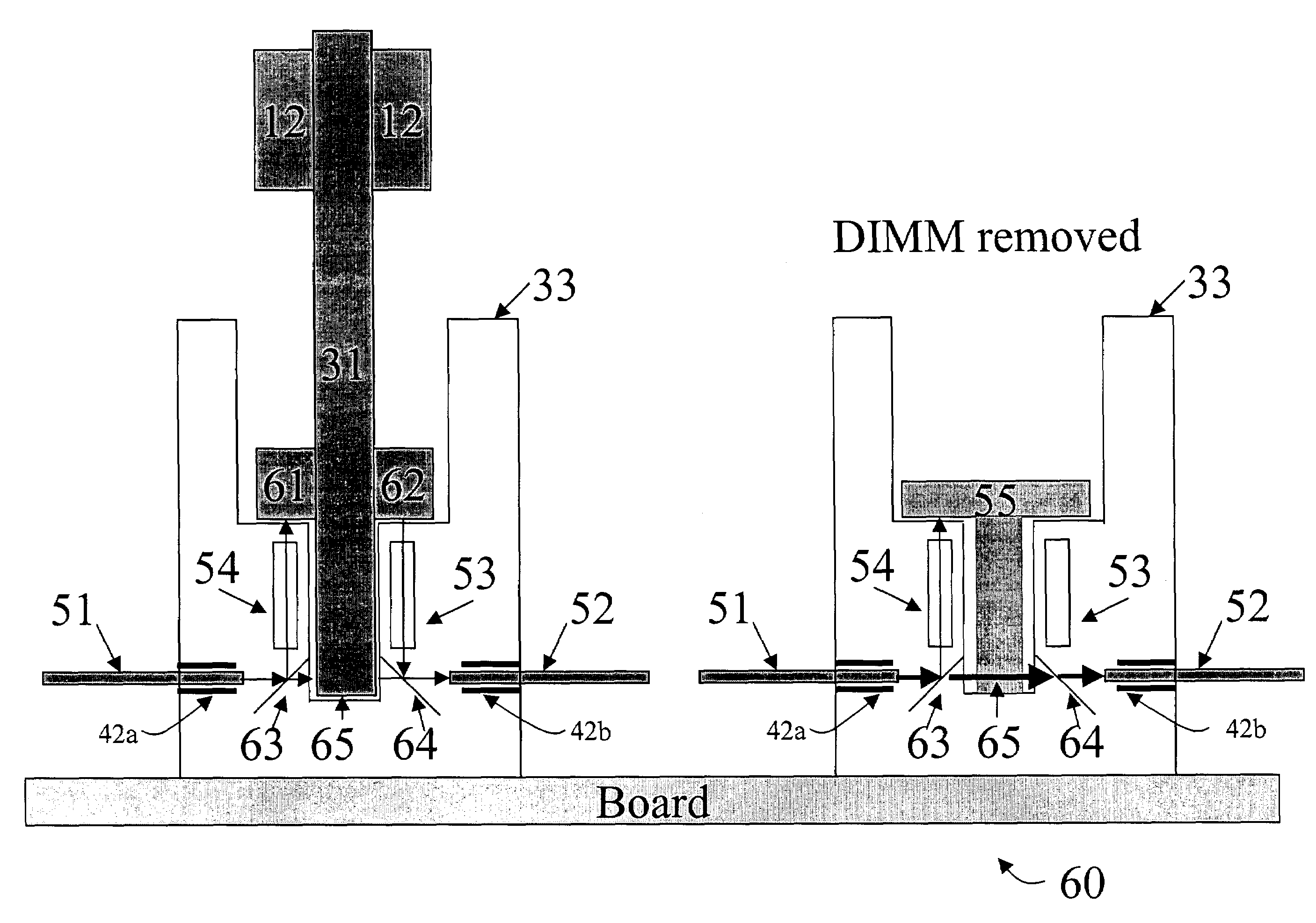
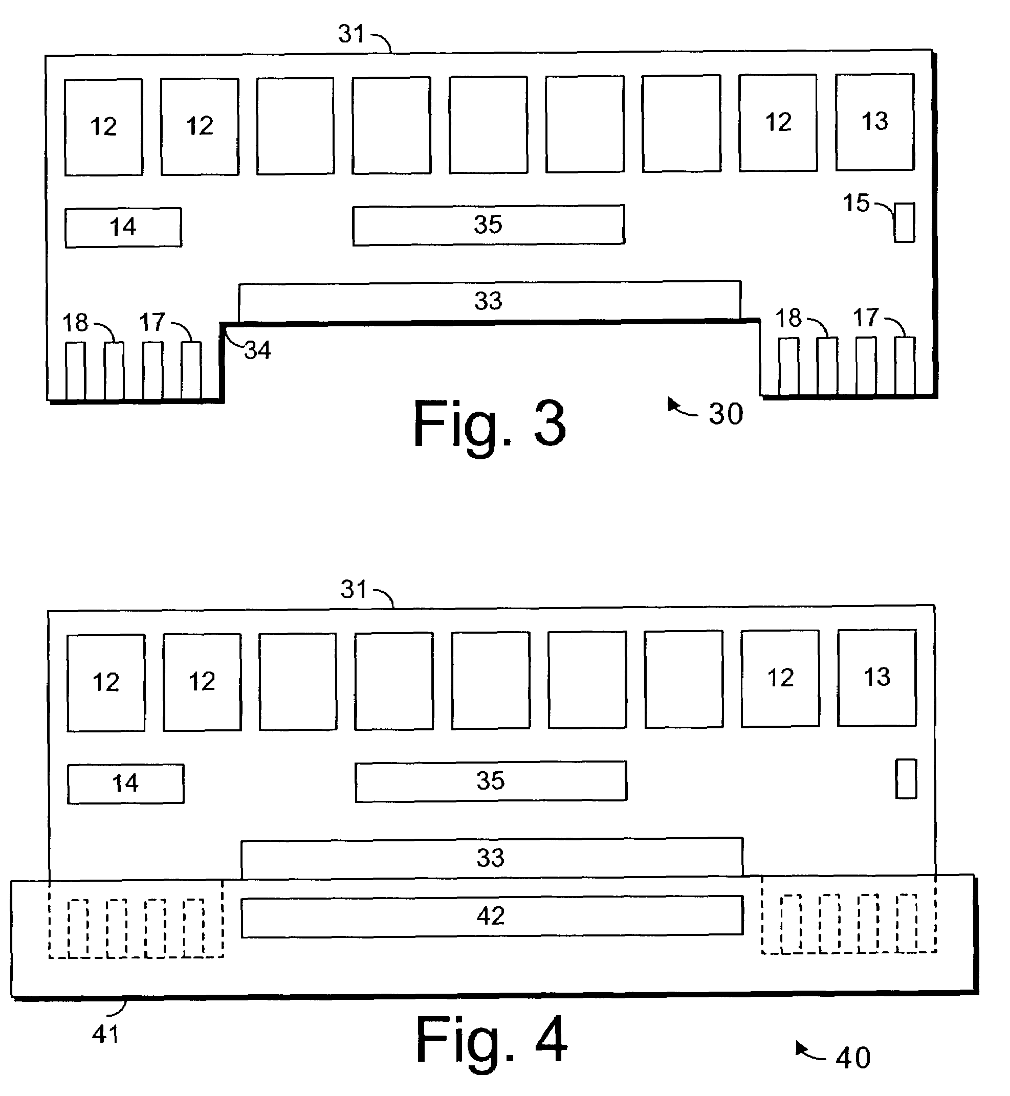
[0018]FIG. 3 illustrates one embodiment of a dual inline memory module (DIMM) 30 having both optical and electrical signals. The DIMM includes a substrate 31, one or more memory devices 12, and optionally one or more support devices 13 and passive components 14, 15. The substrate includes electrical contacts 17, 18 for providing some of the connections of the DIMM and for carrying low-speed data such as control or configuration information to an E-Prom or non-volatile memory. In one embodiment, these contacts provide power, ground, and low-speed signaling such as system management or supervisory signals. In another, they provide only power and ground and may carry low-speed data such as control or configuration information in an E-Prom or non-volatile memory. An optical interface 33 provides a connection for receiving high-speed signals such as data bits, address bits, and so forth. In some embodiments, the substrate includes a cutout 34, which provides an optical path through which...


PUM


Abstract

A system includes multiple agents coupled to an optical bus for transmission of high speed signals and to an electrical bus for transmission of low speed signals. The agents can be memory modules, such as DIMMs. An optical connector housing for coupling the agent to the optical bus can include a reflective device such a mirror, a semi reflective mirror, a pellicle beamsplitter, or the like. The low speed signals can be, for example, power, ground, and supervisory signals. The high speed signals can be, for example, data, address, control, and clock signals.

Description

FIELD[0001]This invention relates generally to optical interconnect systems, and more specifically to a system in which multiple memory modules have electrical power and low-speed data transmitted via e.g. copper wire, and high-speed data transmitted via an optical bus in which the connectors have mirrors or pellicles and the memory modules communicate on the optical bus.DESCRIPTION OF RELATED ART[0002]Optical data transmission systems have, to date, been point-to-point. Multiple optical agents can be connected in series using repeaters or transceivers between each successive pair of adjacent point-to-point optical links.[0003]Electrical busses have limitations on the number of agents, which can be connected to them, before the busses collapse due to diminished signal integrity. Presently, a memory bus is generally capable of supporting only a limited number of memory modules due to deterioration in signal integrity. For example, a computer may be limited to four dual inline memory ...

Claims


Application Information

Patent Timeline
Patent Type & Authority Patents(United States)
IPC IPC(8): H04B10/00G02B6/42
CPCG02B6/4201G02B6/4214G02B6/4246G02B6/4274G02B6/4284
Inventor LEVY, PAUL S.MAURITZ, KARL H.
Owner INTEL CORP
Why Eureka
Try Eureka