
Device for cardiocirculatory assistance

a technology of cardiocirculatory assistance and device, which is applied in the direction of positive displacement liquid engine, piston pump, therapy, etc., can solve the problems of affecting the efficiency of the pump, and causing haemolysis or blood clot formation, etc., to achieve efficient and effective haematic flow, reduce weight, and reduce the effect of weigh

Inactive Publication Date: 2008-05-06
A N B TECH
View PDF5 Cites 11 Cited by
  • Summary
  • Abstract
  • Description
  • Claims
  • Application Information

AI Technical Summary

Benefits of technology

[0009]In view of this state of the art, it was the object of the present invention to obtain a device for cardiocirculatory assistance exhibiting high reliability and having reduced weight and size.
[0011]By means of its special two-membrane pumping system, the haematic pump comprised in the device according to the invention, allows to obtain a particularly efficient and effective haematic flow, as well as exhibiting high reliability, also obtaining on the whole a device having no inertial sussultatory motions, where the periodically pulsing haematic flow provides pulses, which may be synchronous or asynchronous with respect to the heart pulse, the whole driven by an external pneumatic energy generating unit which may have reduced weight and reduced size.

Problems solved by technology

In most cases, the currently existing devices exhibit some difficulties to be accommodated inside the chest, because of problems both with size and weight.
Other drawbacks that can be found therein are caused by their inner configurations and their pumping modes, which may induce haemolysis or blood clot formation.
These devices, as their inherent feature, do not allow blood circulation in the pump, thus avoiding the above mentioned problems.
Another negative aspect of these currently available solutions is represented by the weight and size of the driving units associated with the pumping device, which render the portability, namely the easy transport by the patient, essentially non-existent.

Method used


Image

  • Device for cardiocirculatory assistance
  • Device for cardiocirculatory assistance
  • Device for cardiocirculatory assistance

Examples


Embodiment Construction

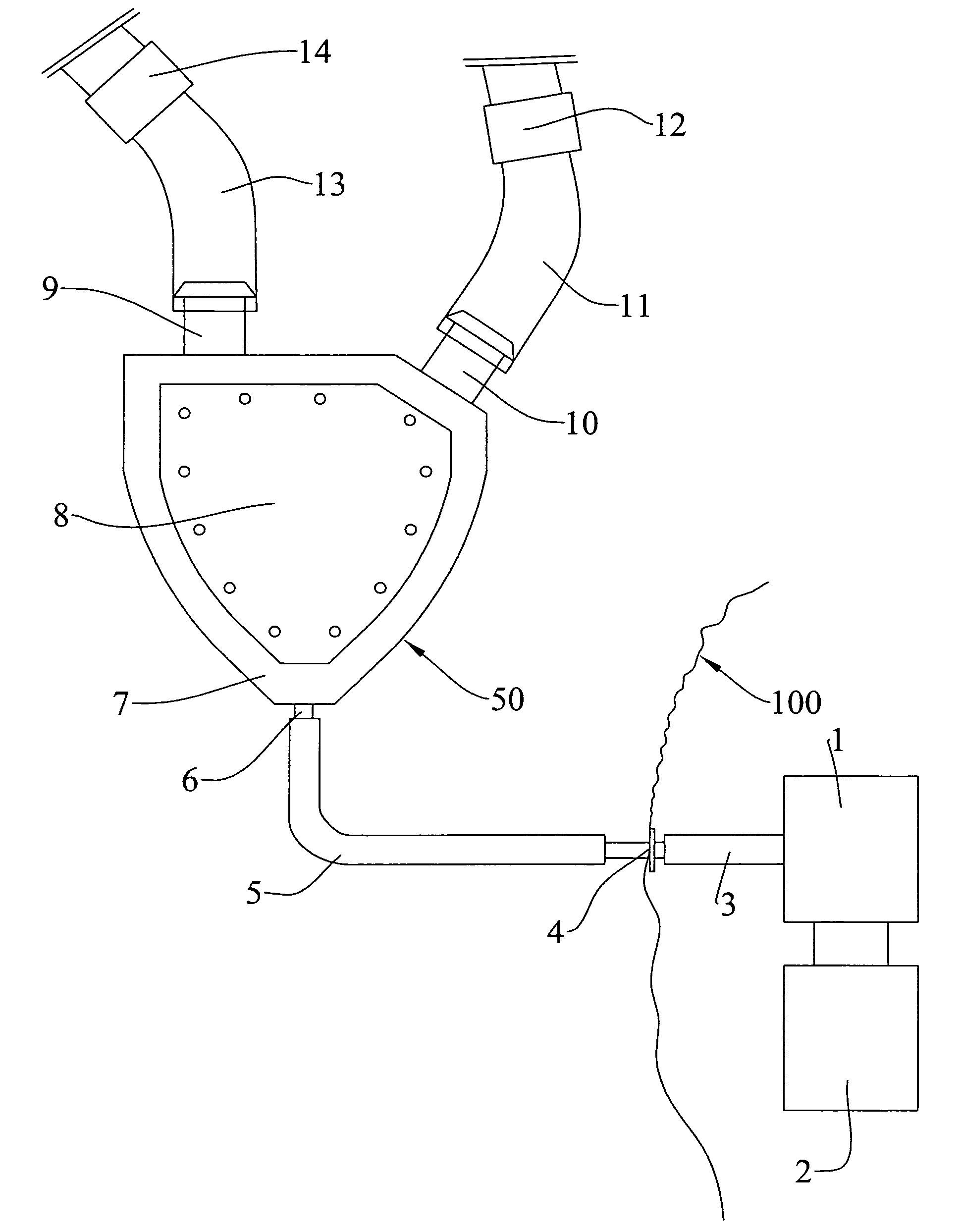
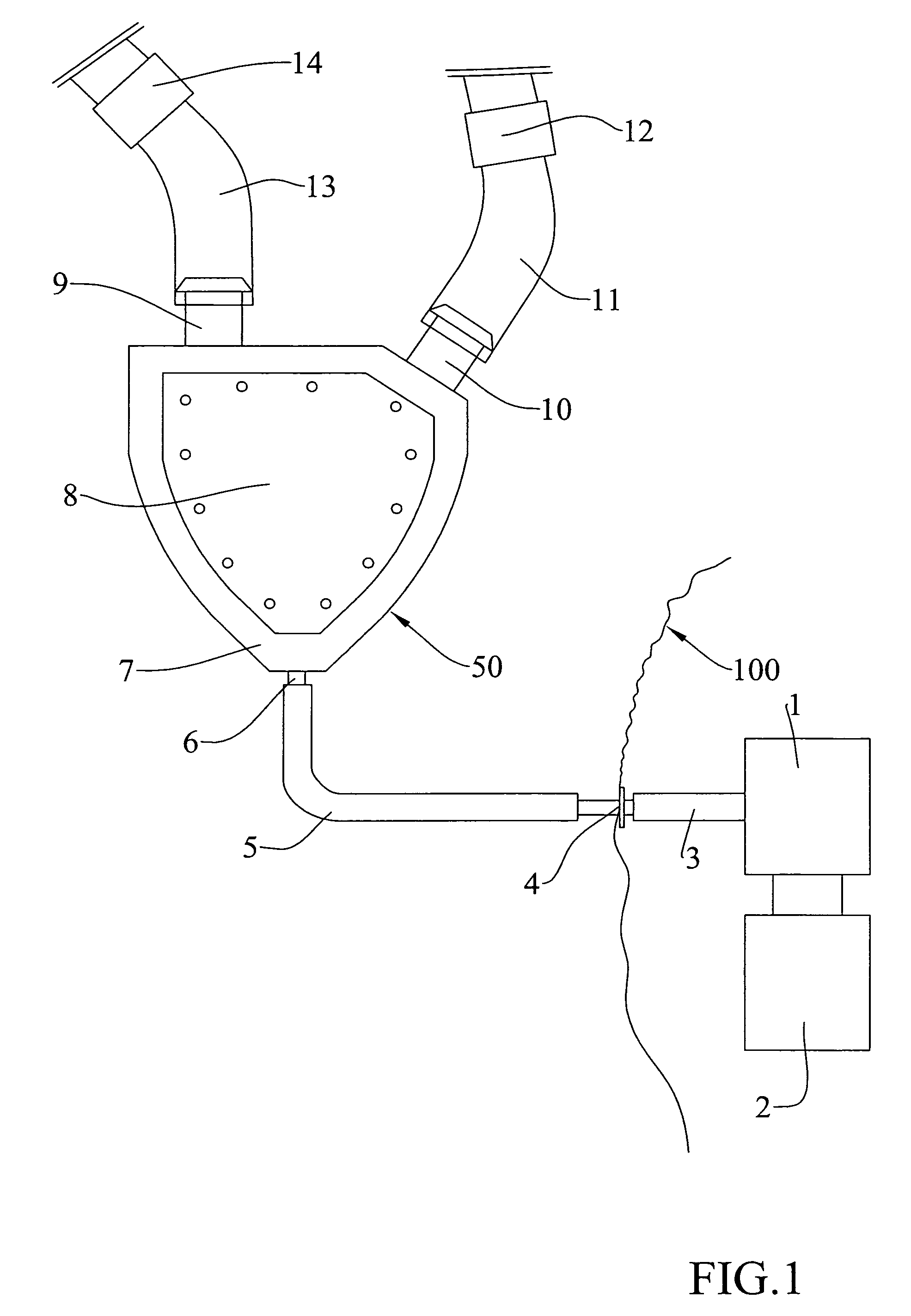
[0020]FIG. 1 shows a diagrammatic drawing of the various components of a device for cardiocirculatory assistance according to the present invention.

[0021]The device comprises a pneumatic energy (gas) generating unit 1 supplied by a battery set 2, which transmits pneumatic energy to a tube 5 positioned inside the body of the patient (generally indicated by reference number 100) through a flexible tube 3 and a transcutaneous implant 4.

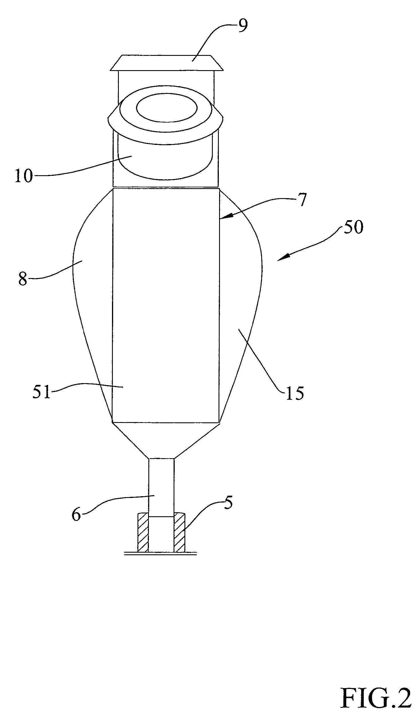
[0022]The inner tube 5 is connected to an input 6 of a haematic pump 50 having a pump body 7 in a haemocompatible material sealed between two rigid protective lids 8 and 15, obtainable in a material compatible with the body tissues of the patient, reciprocally fixed so as to form a single piece, as shown in FIGS. 1, 2 and 3.

[0023]Between the two lids 8 and 15, the pump body 7 envisages two flexible inner membranes 16 and 17 (FIG. 3), defining a substantially cylindrical shaped inner space 21 together with a remaining rigid structure 51 (FIGS. 3, 6 and 7)...


PUM


Abstract

A device for cardiocirculatory assistance, also named a ventricular assist device, includes a haematic pump (50) with a pump body (7) having an inner space (21) defined by a rigid structure (51) and a pair of mobile membranes (16, 17) alternately driven in opposite directions by alternately positive pressure and negative pressure gas supplied to recesses (19, 20) surrounding the two membranes by means of an external pneumatic force generating unit (1). This device achieves excellent operation results while maintaining a reduced size and reduced weight.

Description

FIELD OF THE INVENTION[0001]The present invention relates to a device for cardiocirculatory assistance which is obtained by means of a special haematic pump driven by pneumatic energy.BACKGROUND OF THE INVENTION[0002]It is known that in heart-surgery practice some devices for the mechanical assistance of the heart are used, commonly indicated as “ventricular assist devices (V.A.D.)” or “total artificial hearts (T.A.H.)”.[0003]These are essentially devices adapted to mechanically pump blood to produce pulsing or continuous blood flows.[0004]Such devices are employed to solve acute reversible heart failure clinical cases (as infarct or myocarditis) or are used to support the circulatory function while waiting for a heart transplant.[0005]There have been for years several both left and right ventricular assist devices or biventricular assist devices (T.A.H); some of them are commercially available, others have been developed only at an experimental stage.[0006]In most cases, the curren...

Claims


Application Information

Patent Timeline
IPC IPC(8): A61M35/00A61M60/178A61M60/268A61M60/427A61M60/88A61M60/894
CPCA61M1/106F04B43/06F04B43/10A61M1/1062A61M1/1096A61M1/122A61M60/43A61M60/894A61M60/148A61M60/427A61M60/88A61M60/178
Inventor NARDI, GIANCARLO
Owner A N B TECH
Learn More