Source-antennas for transmitting/receiving electromagnetic waves

a sourceantenna and electromagnetic wave technology, applied in the direction of individual energised antenna arrays, polarised antenna unit combinations, non-resonant long antennas, etc., can solve the problems of unoptimized selection of antenna arrays for reception sources, unfavorable individual use, and unwieldy implementation technology, etc., to simplify the topology of the feed array, reduce the loss of arrays, and reduce the loss

Inactive Publication Date: 2008-05-06
THOMSON LICENSING SA
View PDF12 Cites 196 Cited by
  • Summary
  • Abstract
  • Description
  • Claims
  • Application Information

AI Technical Summary

Benefits of technology

[0016]The use of radiating devices of the travelling wave type, more particularly of helical devices, exhibits a certain number of advantages. Thus, it makes it possible to restrict the array losses, the helical devices exhibiting very low losses. Consequently, the losses from the array-antenna are limited almost to the losses from the feed array. Moreover, they afford a solution to the problems of choosing the substrate. Specifically, in the case of patch-type antennas, compromises are necessary between the demands of circuits requiring a slender substrate with high dielectric permittivity and those of the antennas requiring a thick substrate with low permittivity.
[0017]Moreover, the use of a helical device as elementary radiating element for the array makes it possible by virtue of its intrinsic radiation under circular polarization and of its operation over a wide frequency band to afford a solution to the problems of width of bands and of circular polarization of the source-antenna.
[0018]Furthermore, when the n radiating elements are positioned using the technique of sequential rotation for the array, the use of a helix as elementary radiating element makes it possible to simplify the topology of the feed array, thus restricting its losses and its bulk.

Problems solved by technology

The implementational technology is unwieldy and expensive.
Its weight and bulk are generally incompatible with use by individuals.
However, the reception frequency band generally being wider than the transmission frequency band and the link budget being more sensitive to losses of the reception source, the choice of an array of patches for the reception source is not optimal from this point of view.
Moreover, with an array of patches, it is often difficult to obtain circular polarization of good quality throughout the reception band.

Method used


Image

  • Source-antennas for transmitting/receiving electromagnetic waves
  • Source-antennas for transmitting/receiving electromagnetic waves
  • Source-antennas for transmitting/receiving electromagnetic waves

Examples


Embodiment Construction

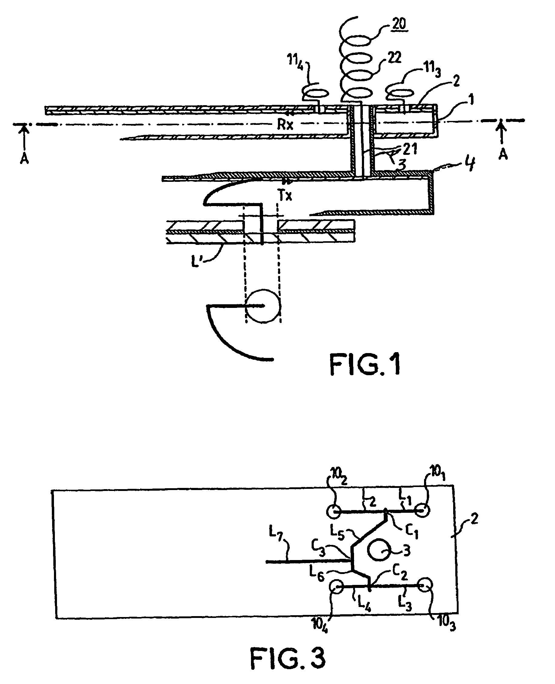
[0029]As represented more particularly in FIGS. 1 and 4, the source-antenna is a mixed source comprising a first array of n radiating elements operating in a first frequency band more particularly in reception and a longitudinal-radiation antenna operating in a second frequency band, i.e. in transmission.

[0030]As represented in FIG. 1, the first array of n radiating elements consists of a support 1 of parallelepipedal shape, covered on its upper face with a substrate 2 made of dielectric materials.

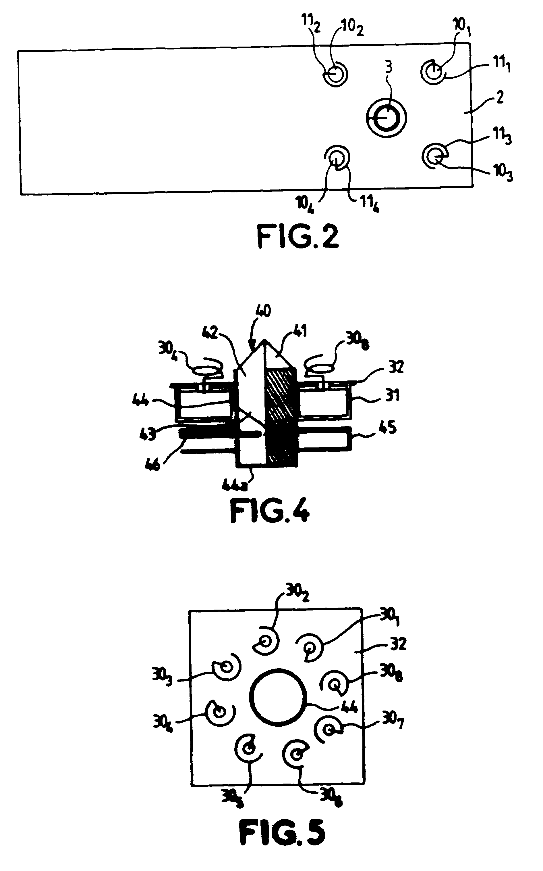
[0031]As represented clearly in FIG. 2, the support 1 comprises four circular holes 101, 102, 103, 104, which, in the embodiment represented, are positioned at the four vertices of a square. These four holes allow the passage of four radiating elements consisting of helices 111, 112, 113, 114. Provided at the middle of the square is a circular aperture allowing the passage of a fastening stem which forms part of the support element of the longitudinal-radiation antenna which will be descri...


PUM


Abstract

The present invention relates to a source-antenna for transmitting / receiving electromagnetic waves comprising an array of n radiating elements (113, 114) operating in a first frequency band, means (20) with longitudinal radiation operating in a second frequency band, the array and the means with longitudinal radiation having a substantially common phase centre, the n radiating elements being arranged symmetrically about the longitudinal-radiation means, and each element (113, 114) of the array consisting of a radiating element of the travelling wave type.

Description

[0001]This application is a continuation of U.S. application No. 09 / 874,340, filed on Jun. 5, 2001 now abandoned.FIELD OF THE INVENTION[0002]The present invention relates to an improvement to source-antennas for transmitting / receiving electromagnetic waves, more particularly to the devices of this type used for satellite communication systems in the C band, in the Ku band or in the Ka band.BACKGROUND OF THE INVENTION[0003]Interactive wireless telecommunication services are developing ever more rapidly. These services relate in particular to telephony, telefax, television, the Internet network and any so-called multimedia domain. The equipment for these general-broadcast services have to be available at reasonable cost. This is true in particular for the user's transmission / reception system which has to communicate with a server, usually by way of a telecommunication satellite. In this case, the communications are performed in the microwave frequency domain, especially in the C, Ku o...

Claims


Application Information

Patent Timeline
Patent Type & Authority Patents(United States)
IPC IPC(8): H01Q1/36H01Q21/00H01Q21/30H01Q1/38H01Q5/00H01Q5/47H01Q11/08H01Q13/24H01Q21/20H01Q21/24H01Q21/28
CPCH01Q11/08H01Q13/24H01Q5/47H01Q21/067H01Q21/28
Inventor HIRTZLIN, PATRICELOUZIR, ALIPINTOS, JEAN-FRANCOISTHUDOR, FRANCK
Owner THOMSON LICENSING SA
Why Eureka
Try Eureka