Processor for analyzing tubular structure such as blood vessels

a tubular structure and processing technology, applied in the field of processing for analyzing a tubular structure, can solve the problems of x-ray angiographic imaging at present being inadequate at rendering capillaries, diagnosis tends to underestimate the degree of blood vessel stenosis, and limited topological abnormality assessment based on this imaging. to achieve the effect of reducing the operational burden

Inactive Publication Date: 2008-05-06
TOSHIBA MEDICAL SYST CORP
View PDF10 Cites 212 Cited by
  • Summary
  • Abstract
  • Description
  • Claims
  • Application Information

AI Technical Summary

Benefits of technology

[0021]The present invention was developed in view of the various problems in the conventional observing and analyzing methods of a tubular structure (tubular system) as described above, and has a main object to provide a processor for analyzing a tubular structure that permits easy grasping of the entire and partial three-dimensional shape of a tubular structu

Problems solved by technology

Since X-ray imaging is two-dimensional, assessment of a topological abnormality based on this imaging is limited.
For example, when using X-ray images taken in one direction, the diagnosis tends to underestimate the degree of blood vessel stenosis.
X-ray angiographic imaging at present is inadequate at rendering capillaries.
However, since a tubular structure such as a blood vessel has a complex shape because of the generally complex three-dimensional complex path, it is difficult to identify the position or the state of a disease such as stenoses and lumps even when observing a pseudo-three-dimensional displayed image (such as a volume-rendering image).
When observing a two-dimensional image on an arbitrary sectional surface, on the other hand, it is very difficult to accurately set a sectional position, and this has imposed a burden on the operator, such as a physician.
Firstly,

Method used


Image

  • Processor for analyzing tubular structure such as blood vessels
  • Processor for analyzing tubular structure such as blood vessels
  • Processor for analyzing tubular structure such as blood vessels

Examples


first embodiment

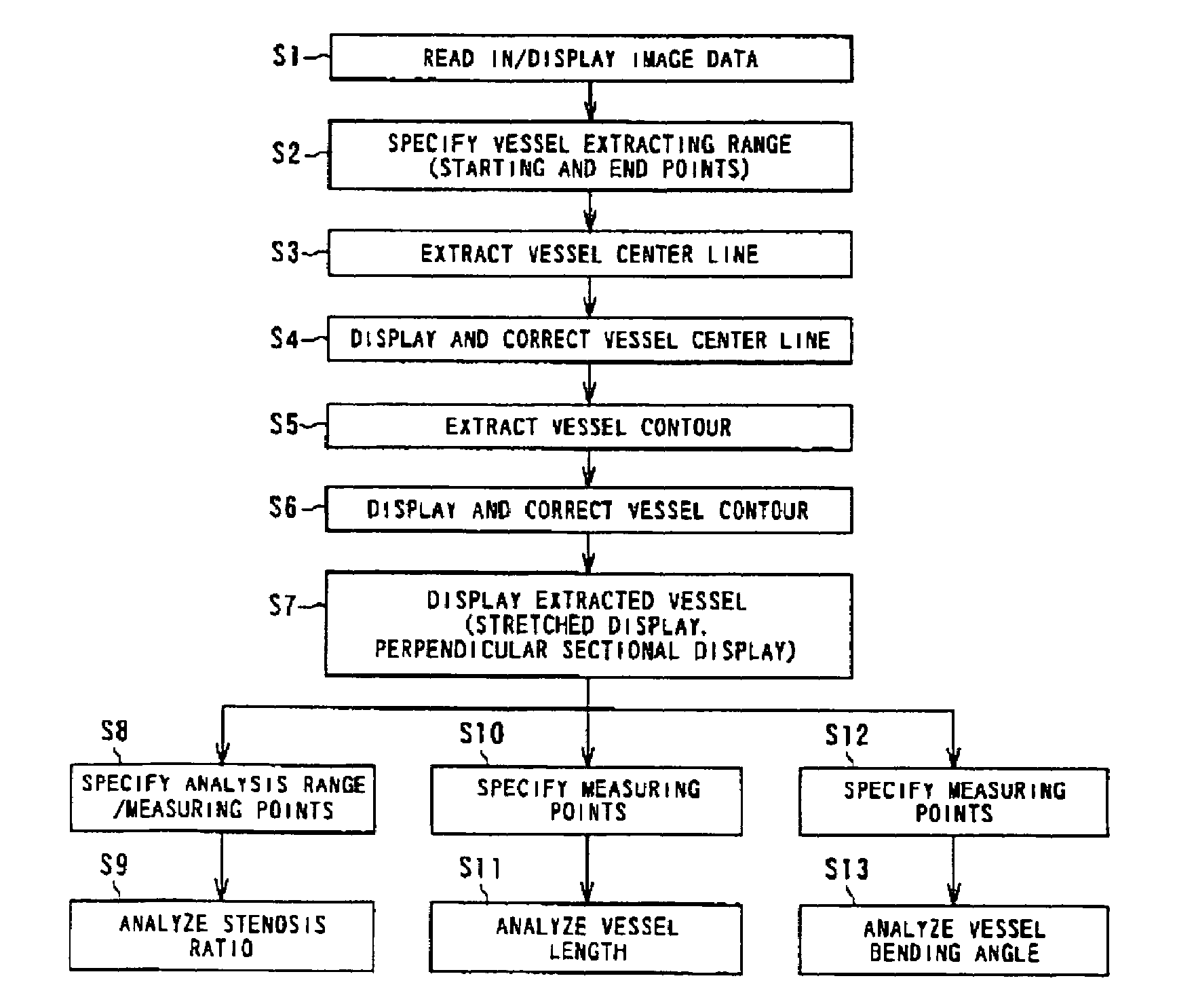
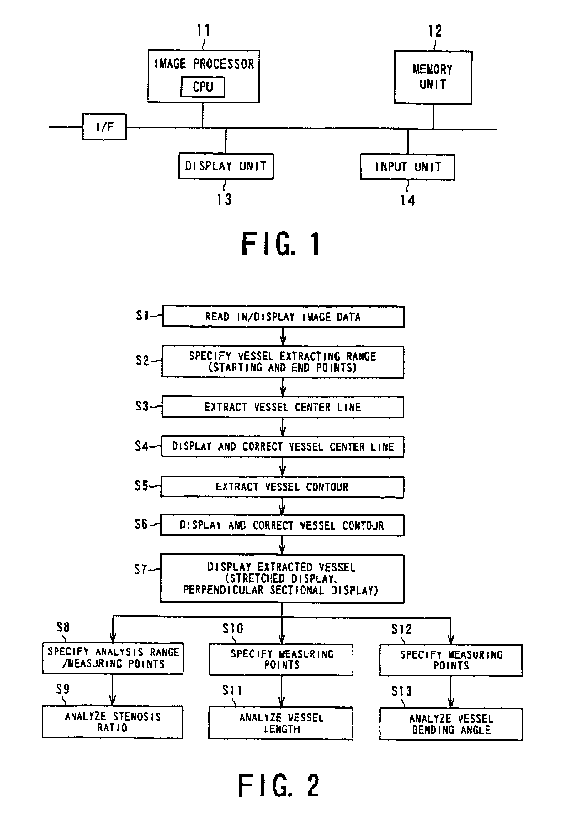
[0073]A first embodiment will be described with reference to FIGS. 1 to 14.

[0074]As shown in FIG. 1, the image processor of this embodiment is provided as a computer device connected online to a medical modality via a communication line as a computer device incorporated integrally with the medical modality, or as an offline computer device separately from the medical modality.

[0075]As shown in FIG. 1, this computer device comprises an image processor 11 including a CPU and a memory, a memory unit 12 storing programs and processed data, a display unit 13, and an input unit 14. As described above, the computer device has a function of performing data communication with outside as required.

[0076]Three-dimensional (solid-body) image data of a subject collected by a diagnostic imaging apparatus (medical modality), such as an X-ray CT scanner or an MRI, are sent online or offline to the memory unit 12. These three-dimensional image data are stored in a large-capacity memory medium, such a...

second embodiment

[0210]A second embodiment of the processor for analyzing a tubular structure of the present invention will be described with reference to FIGS. 24 to 33.

[0211]This embodiment provides a processor for analyzing a tubular structure which permits efficient identification of the sectional shape in the three-dimensional display of a vessel image, particularly observation of portions around a stenosis site and the position in the whole blood vessels. More specifically, the processor for analysis has a function permitting correction of the contour of an extracted area in a vessel stretched image, a straight view, and a perpendicular sectional image, a perpendicular view; a function to display in parallel a stenosis ratio curve on the vessel stretched image; a function to cut an area to be analyzed and three-dimensionally display the cut area; a jumping function of the image display position, and a parametric display function.

[0212]The processor for analyzing a tubular structure in this emb...

third embodiment

[0300]A third embodiment of the processor for analyzing a tubular structure of the present invention will now be described with reference to FIGS. 34 to 40.

[0301]This embodiment is intended to permit identification of the sectional shape in the three-dimensional display of a vessel image, particularly, easy and accurate identification of the three-dimensional secular change in lumps in the blood vessel to improve the accuracy determination of adaptability to surgery. The processor for analyzing of this embodiment is schematically based on the process comprising the steps of extracting the vessel center line and vessel areas (including blood vessel lumens and blood clot site) from present and past three-dimensional image data; specifying the measuring range; specifying branching position serving as a reference before and after the measuring range and aligning the positions; and carrying out a quantitative analysis and display of the result of analysis regarding lumps on the basis of ...


PUM


Abstract

Using medical three-dimensional image data, at least one of a volume-rendering image, a flat reformatted image on an arbitrary section, a curved reformatted image, and an MIP (maximum value projection) image is prepared as a reference image. Vessel center lines are extracted from this reference image, and at least one of a vessel stretched image based on the center line and a perpendicular sectional image substantially perpendicular to the center line is prepared. The shape of vessels is analyzed on the basis of the prepared image, and the prepared stretched image and/or the perpendicular sectional image is compared with the reference image, and the result is displayed together with the images. Display of the reference image with the stretched image or the perpendicular sectional image is made conjunctive. Correction of the center line by the operator and automatic correction of the image resulting from the correction are also possible.

Description

BACKGROUND OF THE INVENTION[0001]1. Field of the Invention[0002]The present invention relates to a processor for analyzing a tubular structure. More particularly, the present invention relates to a processor for analyzing a tubular structure which permits three-dimensional observation, in a diagnostically useful manner, of a tubular structure (system) such as blood vessels, the intestine, the windpipe, and the esophagus on the basis of three-dimensional imaging data of a patient captured by a diagnostic medical imaging apparatus (medical modality), and quantitative analysis of indices useful for diagnosis, including the thickness (including local changes such as stenoses and lumps) or the length of a tubular structure.[0003]2. Description of the Related Art[0004]It has been conventional practice in the diagnosis of blood vessels, to take X-ray images while administering an angiographic agent to a patient, in order to detect the presence of abnormalities on the basis of the image val...

Claims


Application Information

Patent Timeline
IPC IPC(8): G06K9/00G01R33/32A61B5/00A61B5/055A61B6/03A61B8/00G06T1/00G06T15/08G06T19/00
CPCG06T15/08G06T7/0083G06T2215/06G06T2207/30172G06T7/12
Inventor KONDO, YASUHIRAOHYU, SHIGEHARUYAMAGATA, HITOSHICALDERON, ARTUROKAWASAKI, TOMOHIROSUGIYAMA, ATSUKO
Owner TOSHIBA MEDICAL SYST CORP
Why Eureka
Try Eureka