
System for reducing the electromagnetic interference between two or more antennas coupled to a wireless communication device

Active Publication Date: 2008-05-06
ZEBRA TECH CORP
View PDF6 Cites 27 Cited by
  • Summary
  • Abstract
  • Description
  • Claims
  • Application Information

AI Technical Summary

Benefits of technology

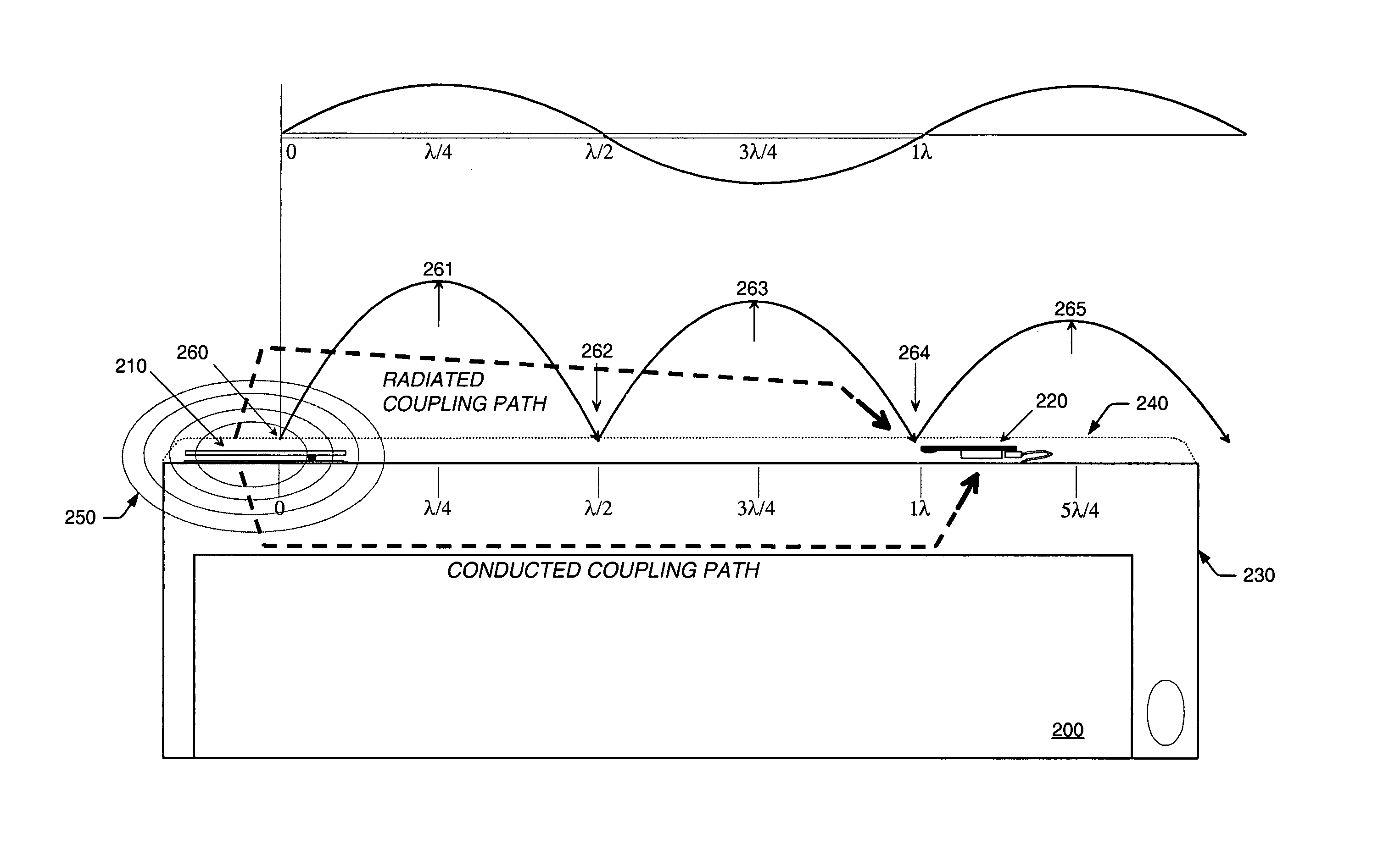
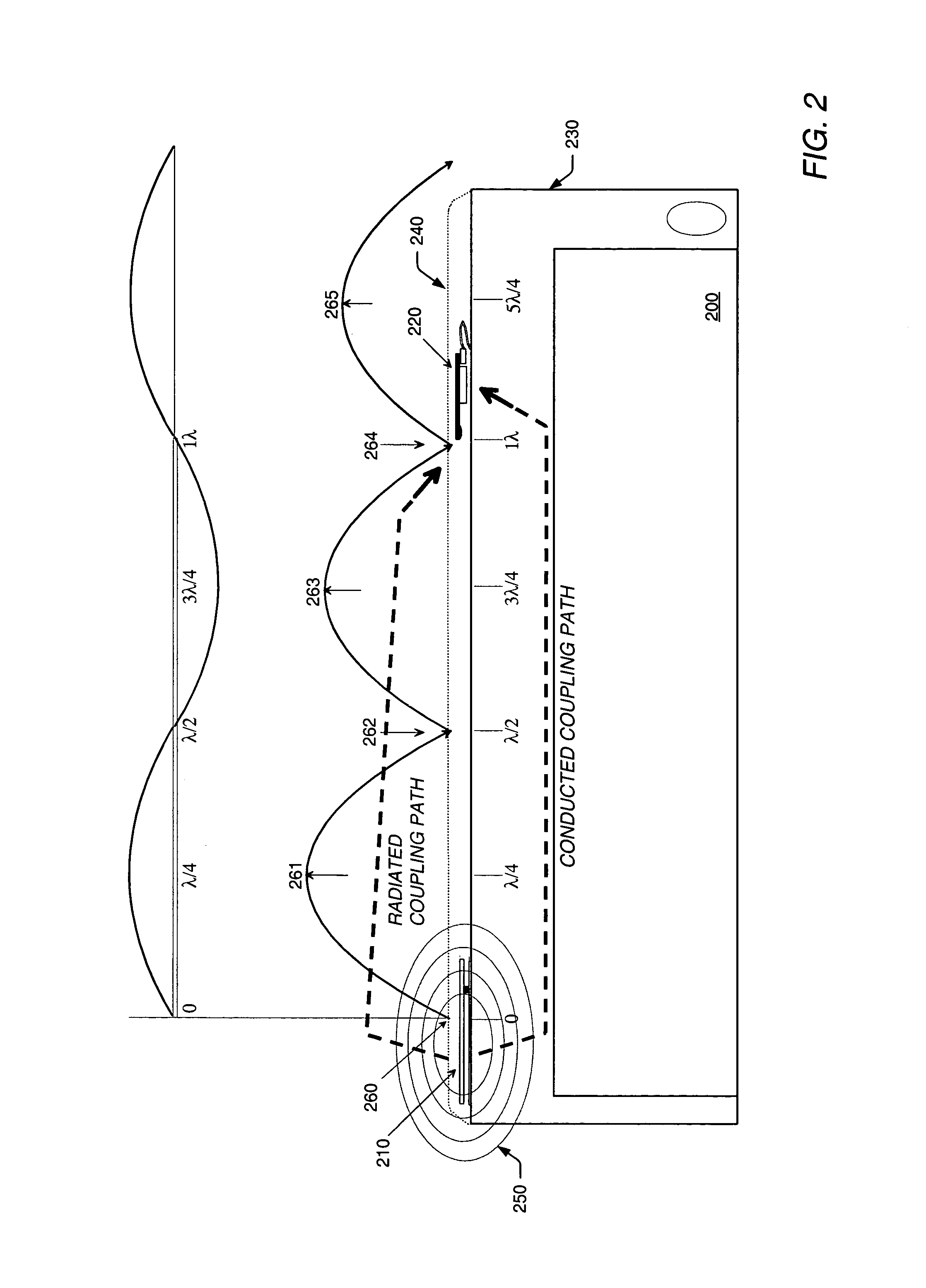
[0024]In a particular embodiment, the plurality of resonant circuit elements may reduce interference by forming a periodic surface that resonates with the electromagnetic energy radiated from one of the antennas to produce a plurality of standing wave patterns, which then combine to redirect at least a portion of the electromagnetic energy away from the other antenna. In some cases, the plurality of resonant circuit elements may be specifically designed (with capacitive and inductive portions) to produce the plurality of standing wave patterns at about the carrier frequency of the first signal. If one or more of the antennas use different transmission frequencies, however, the plurality of resonant circuit elements are preferably designed to produce standing wave patterns at the lowest carrier frequency used by the antennas.
[0027]The apparatus may be formed from an electrically conductive material. In some cases, the conductive material may be selected from substantially any metal or metal alloy. In most cases, however, the conductive material is preferably selected from an assortment of ferrous-based materials, since a primary goal of the apparatus is to reduce the radiated (or magnetic) component of an incoming electromagnetic wave. In some cases, conductive materials within a particular range of relative permittivity and relative permeability values may be chosen to effectively reduce the magnetic components of the electromagnetic wave. For example, the selected material may have a relative permittivity (∈r) of about 0.0 F / m to about 1.0 F / m. Additionally, the selected material may have a relative permeability (μr) of about 10 H / m to about 100,000 H / m.
[0030]A method is also disclosed herein for reducing the electromagnetic interference between two or more antennas coupled to a wireless communication device. As noted above, electromagnetic interference may occur at a second antenna due, in part, to the close proximity of the second antenna to a first antenna.
[0038]By redirecting or scattering the radiated energy, the present method may reduce interference at the second antenna while conserving the energy radiated from the first antenna, and vice versa. In other words, the steps of providing the apparatus and coupling the apparatus may enable electromagnetic interference to be reduced without absorbing the electromagnetic energy radiated from the first antenna or decreasing a transmission power level of the transmitted signal. In some embodiments, the steps of providing the apparatus and coupling the apparatus may also provide an insertion loss of about −25 dB to about −35 dB between the first and second antennas. This insertion loss may be provided throughout the entire range of band-gap frequencies.

Problems solved by technology

As will be described in more detail below, interference often occurs whenever a radio receives, in addition to a desired signal, the signals from other radios transmitting within the same (or a nearby) radio frequency band.
The term “close proximity” may then refer to a distance, which separates two or more co-located radio modules and results in an unacceptable level of interference when the radios are simultaneously operated within the same (or nearby) radio frequency band.
In either case, interference may occur when electromagnetic energy radiated from one of the antennas is received by the other antenna.

Method used


Image

  • System for reducing the electromagnetic interference between two or more antennas coupled to a wireless communication device
  • System for reducing the electromagnetic interference between two or more antennas coupled to a wireless communication device
  • System for reducing the electromagnetic interference between two or more antennas coupled to a wireless communication device

Examples


Embodiment Construction

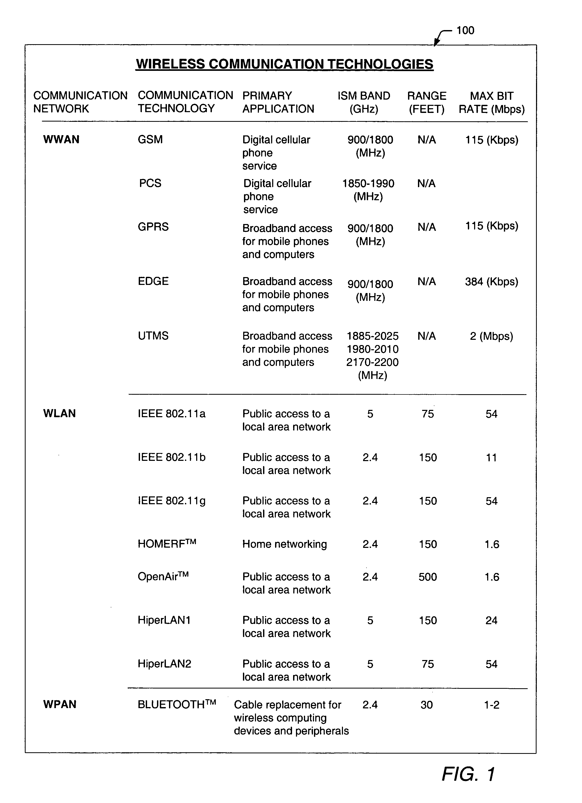
[0066]A current trend in wireless telecommunications is the integration of two or more wireless communication technologies within a single communications device. For example, PDA manufacturers have been adding WWAN (e.g., GSM / PCS and GPRS) and WLAN (e.g., IEEE 802.11b and HomeRF™) capabilities to their portable computing devices, thereby enabling the devices to transmit voice communications, in addition to providing broadband wireless access in corporate / home environments and WLAN hotspots. Computer manufacturers have also been adding WLAN (e.g., IEEE 802.11b and HomeRF™) and WPAN (e.g., Bluetooth™) capabilities to portable PCs, providing broadband access to WLANs and wireless connectivity to a growing number of WPAN-equipped devices. By combining two or more different communication technologies, the consumer is afforded greater mobility, accessibility and versatility within a single communication device.

[0067]Chart 100 of FIG. 1 illustrates a few examples of currently available wir...


PUM


Abstract

A system for reducing electromagnetic interference between two or more co-located antennas is described herein. In one embodiment, the system includes a first antenna for transmitting a first signal within a first frequency band, and a second antenna for operating within a second frequency band during transmission of the first signal. The first and second frequency bands may be substantially identical, or may occupy overlapping or nearby channels within the radio frequency spectrum. The system also includes an apparatus. In one embodiment, the apparatus is positioned proximate to the second antenna for intercepting the electromagnetic energy radiated from the first antenna during transmission of the first signal. In other embodiments, the apparatus may be positioned proximate to the first antenna for intercepting the electromagnetic energy radiated from the second antenna during transmission of a second signal. In either embodiment, the apparatus is able to reduce electromagnetic interference between the first and second antennas by scattering (or redirecting) radiated energy away from either the first antenna or the second antenna.

Description

BACKGROUND OF THE INVENTION[0001]1. Field of the Invention[0002]This invention relates to wireless communication technologies and, more particularly, to an apparatus and method for reducing radiated electromagnetic coupling between two or more antennas coupled to a wireless communications device.[0003]2. Description of the Related Art[0004]The following descriptions and examples are not admitted to be prior art by virtue of their inclusion within this section.[0005]The term “wireless” is often used to describe telecommunications in which electromagnetic waves (rather than some form of wire) carry a transmitted signal over part or all of the communication path. Some monitoring devices, such as intrusion alarms, employ acoustic waves at frequencies above the range of human hearing; these are also sometimes classified as wireless.[0006]As wireless communication technologies continue to evolve and mature, a growing number of wireless communication devices are becoming available. Example...

Claims


Application Information

Patent Timeline
IPC IPC(8): H04M1/00
CPCH01Q1/521H04B15/02
Inventor STEIGERWALD, TODD W.MAYFIELD, JERRY
Owner ZEBRA TECH CORP
Features
  • Generate Ideas
  • Intellectual Property
  • Life Sciences
  • Materials
  • Tech Scout
  • Unparalleled Data Quality
  • Higher Quality Content
  • 60% Fewer Hallucinations
Learn More