
Batch execution engine with independent batch execution processes

a batch execution and batch technology, applied in the field of process control networks, can solve the problems of halting the throughput of the process plant, affecting the performance of the batch execution engine, and affecting so as to reduce the effect of the software failur

Active Publication Date: 2008-05-06
FISHER-ROSEMOUNT SYST INC
View PDF21 Cites 34 Cited by
  • Summary
  • Abstract
  • Description
  • Claims
  • Application Information

AI Technical Summary

Benefits of technology

The process control system described in this patent allows for the creation of individual processes for each batch of material to be run in a process plant. These processes are executed in separate application spaces, reducing the impact of software failures and allowing for changes to the process equipment model without affecting the current operation of existing processes. Additionally, each process is not affected by limitations imposed by the operating system on individual processes. The technical effect of this system is improved process control and flexibility in managing complex processes.

Problems solved by technology

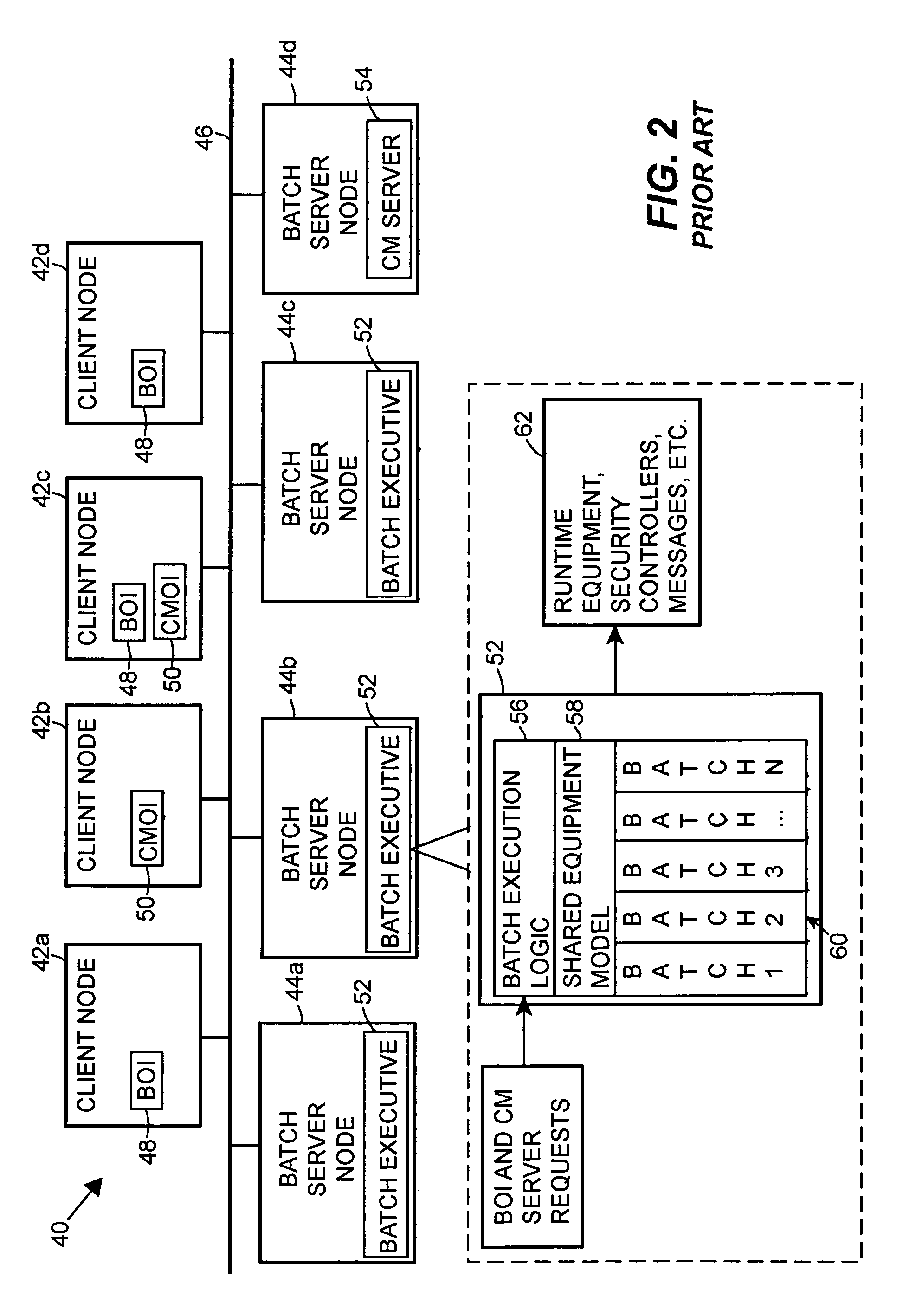
Unfortunately, some batch executive applications are programmed in such a way that a software failure encountered during any one of the batch runs may cause the batch executive application to “crash” or halt, which will generally cause all of the batches that are currently running under the control of the batch executive application to stop or halt.
A crash of the batch executive application may result in the halting the throughput of the process plant and the need for an operator to manually restart all of the batch runs again.
Such restart activities may take an inordinate amount of time to perform while the executive restores each batch to its previous state before the time of the crash and re-synchronizes to the underlying control system.
Needless to say, this activity creates a large amount of downtime in the process plant and a lot of additional work for the operator.
A crash of the batch executive application may also result in one or more of the batches that are in process plant at the time of the crash being scrapped, which may result in significant financial loss in terms of both wasted materials and lost plant operational time.
Still further, it is difficult, if not impossible to modify the configuration of the process equipment model used by known batch executive applications while this application is operating or executing within the process plant because each of the different batches being run by the batch executive application refer to or use this equipment model to make decisions as to the equipment to be used.
As will be understood, this activity has potentially adverse effects on all of the batches whose execution is currently being controlled by the batch executive application.
Additionally, most operating software, such as the Microsoft Windows operating software, limits the amount of physical and virtual memory that can be addressed or used by any particular (single) application.
This feature necessarily limits the number of batches, especially large or complex batches having complex recipes, that can be run or executed simultaneously by the batch executive application because each new batch being run increases the memory requirements of the batch executive application.
While this memory constraint is not usually a problem in most smaller scale process plants, this constraint forces batch executive applications in very large process plants to be limited in the number of concurrent batches which they can execute.
However, using such a work around means that the different batch executive routines (which run as separate applications) are not able to share or coordinate the usage of the process equipment in the most economical or optimal manner.

Method used


Image

  • Batch execution engine with independent batch execution processes
  • Batch execution engine with independent batch execution processes
  • Batch execution engine with independent batch execution processes

Examples


Embodiment Construction

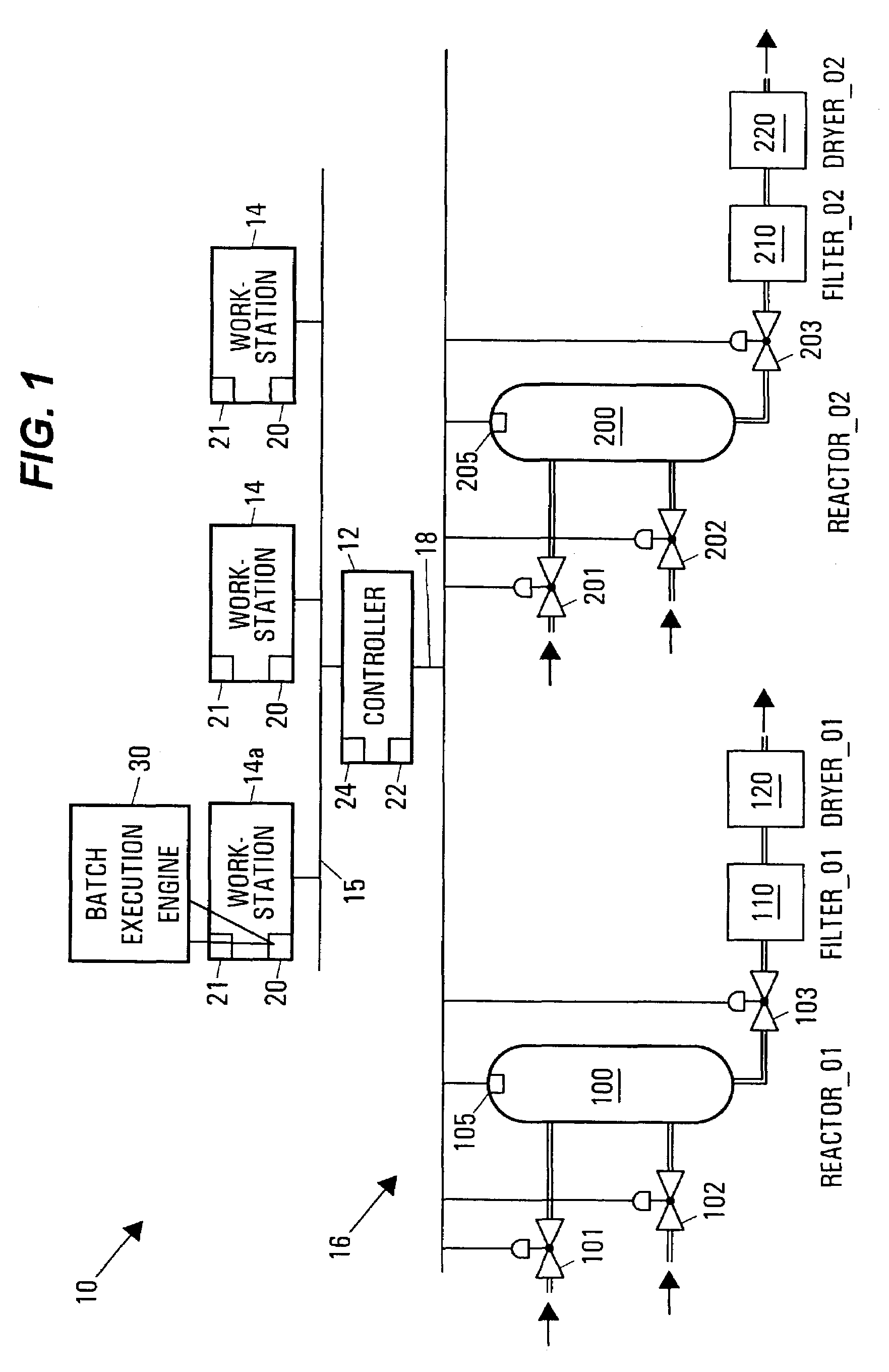
[0014]Referring now to FIG. 1, a process plant control network 10 includes a process controller 12 coupled to numerous workstations 14 via, for example, an Ethernet communications connection 15. The controller 12 is also coupled to devices or equipment within a process plant (generally designated by the reference numeral 16) via an input / output (I / O) device (not shown) and a set of communication lines or a bus 18. The controller 12, which may be by way of example only, the DeltaV™ controller sold by Fisher-Rosemount Systems, Inc., is capable of communicating with control elements, such as field devices and function blocks within field devices distributed throughout the process plant 16 to perform one or more process control routines to thereby implement desired control of the process plant 16. These process control routines may be continuous or batch process control routines or procedures. The workstations 14 (which may be, for example, personal computers, servers, etc.) may be used...


PUM


Abstract

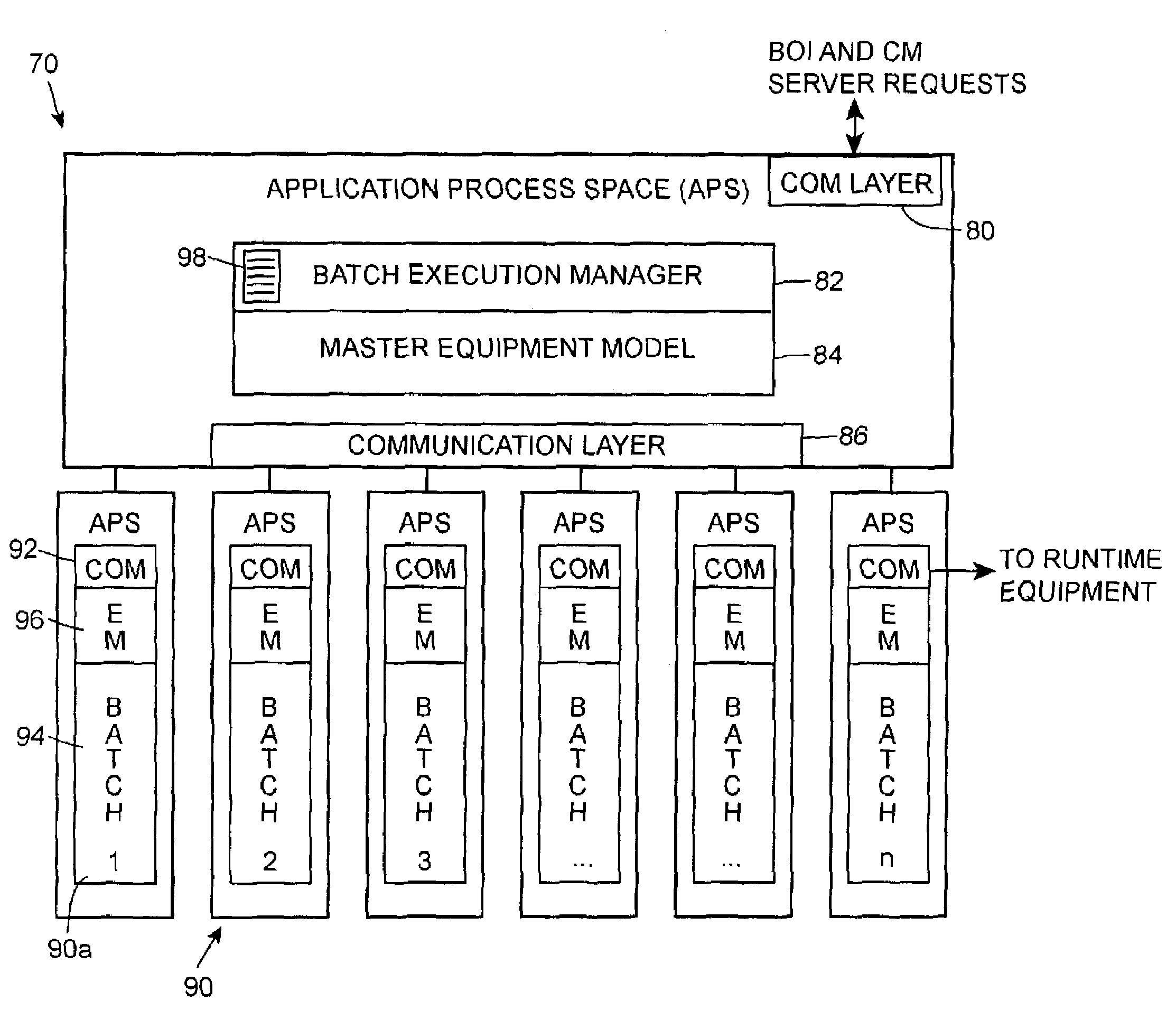
A process plant control system includes a batch execution engine that spawns or creates an individual batch process application in a separate application process space for each batch to be run within a process plant. The batch execution engine includes communication software for communicating with batch operator interfaces used to set up batch runs, a master process equipment model reflecting the current state of the equipment and a batch execution manager that creates individual batch processes and spawns each of the individual batch processes to run in a separate application process space. Each of the created batch processes includes batch logic that implements the batch run specified by the user, a copy of the process plant equipment model used to select equipment within the plant and a communication interface for communicating with controllers and other runtime equipment to implement the batch as well as for communicating with the batch execution manager.

Description

FIELD OF TECHNOLOGY[0001]The present invention relates generally to process control networks and, more particularly, to a batch execution engine that implements independent batch processes in a process plant.DESCRIPTION OF THE RELATED ART[0002]Process control networks, such as those used in chemical, petroleum or other processes, generally include a centralized process controller communicatively coupled to one or more field devices which may be, for example, valve positioners, switches, sensors (such as temperature, pressure and flow rate sensors), etc. These field devices may perform physical control functions within the process plant (such as opening or closing a valve), may take measurements within the process plant for use in controlling the operation of the process plant or may perform any other desired function within the process plant. Process controllers have historically been connected to field devices via one or more analog signal lines or buses which may carry, for exampl...

Claims


Application Information

Patent Timeline
Patent Type & Authority Patents(United States)
IPC IPC(8): G06F19/00G06F9/46G05B15/02G05B11/01G05B19/418G05B19/42G06F9/38
CPCG05B19/41865G05B2219/32077Y02P90/02G05B19/41835G06F9/38
Inventor SHERRIFF, GODFREY R.IRWIN, WILLIAM G.DEITZ, DAVID L.WILSON, GRANTPETTUS, NATHAN W.
Owner FISHER-ROSEMOUNT SYST INC
Learn More