Scanning probe microscope using a surface drive actuator to position the scanning tip

a surface drive actuator and scanning probe technology, applied in the direction of material analysis using wave/particle radiation, generators/motors, instruments, etc., can solve the problems of limited scanning speed, limited acceleration available to accelerate the tip, and limitations of the piezoelectric actuator. achieve the effect of improving the state of the ar

Inactive Publication Date: 2008-05-13
KEYSIGHT TECH
View PDF3 Cites 19 Cited by
  • Summary
  • Abstract
  • Description
  • Claims
  • Application Information

AI Technical Summary

Problems solved by technology

Unfortunately, these piezoelectric actuators have limitations due to creep and resonant frequencies.
When scanning a probe over a surface, the scan speed is limited by several factors such as tip wear, sample abrasion, cantilever response time, detector sensitivity, software acquisition times, external vibrations, available scanning speed, and the acceleration available to accelerate the tip normal to the surface, among others.
However, the acceleration available to accelerate the tip is still extremely limited, being on the order of only several times the acceleration of gravity (g) for conventional scanning probes.
When the piezoelectric actuator is used to displace a scanning microscope probe tip, the scan speed is limited.
This limits the scan rate achievable with the piezoelectric actuator.
The large mass of the z actuator reduces the scan speed that the x-y stage can produce.
Furthermore, control of such actuators can be difficult and renders the overall scanning probe microscope more complex.

Method used


Image

  • Scanning probe microscope using a surface drive actuator to position the scanning tip
  • Scanning probe microscope using a surface drive actuator to position the scanning tip
  • Scanning probe microscope using a surface drive actuator to position the scanning tip

Examples


embodiment 300

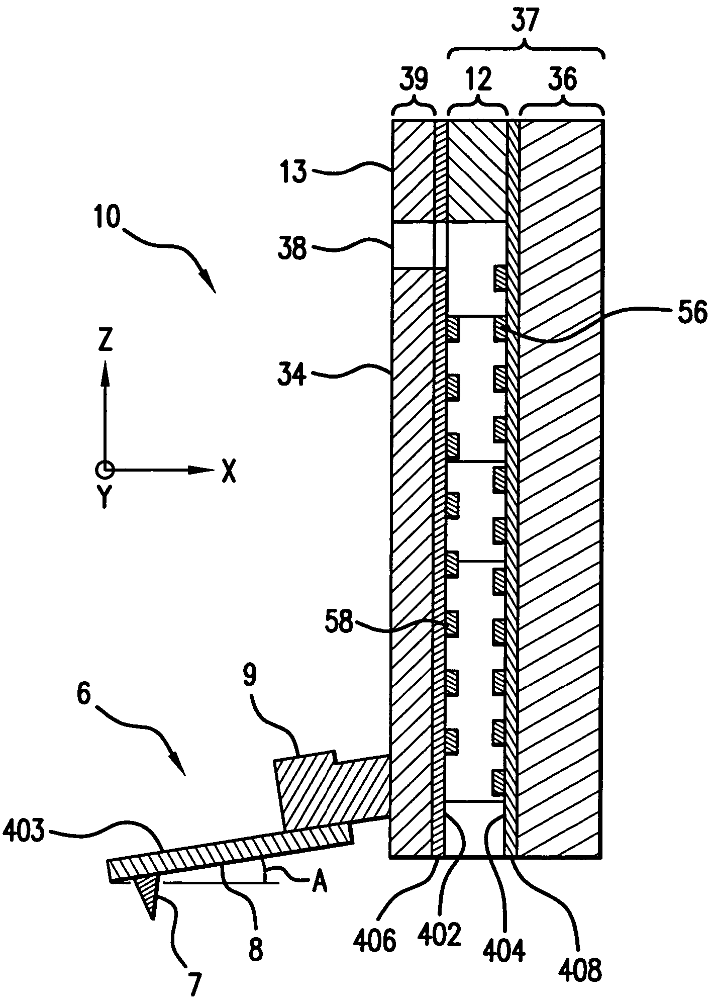
[0067]In some instances, it is desirable to operate Z actuator 10 in a humid or aqueous environment. Water, since it is a polar molecule, tends to shield the electrostatic potentials produced by the stator electrodes 56 and translator electrodes 58 and reduces the forces induced by the Z actuator 10. The embodiment 300 of FIG. 16 circumvents this problem by interposing a layer of dielectric fluid 310 between the translator 34 and stator 36. A suitable dielectric fluid is sold by the 3M company under the trade name FLUORINERT.

Transformer oils are also suitable; one such oil is sold by the Shell Oil Corporation under the trade name DIALA Oil M.

embodiment 350

[0068]A further embodiment 350 for protecting the electrodes from a water environment is shown in FIG. 17. In this case, a hydrophobic dielectric film 355 is coated on parts of the Z actuator 10 exterior to the stator electrodes 56 and translator electrodes 58. Because the gaps between the surfaces are very small, ranging from 100 microns to 1 micron, liquid water cannot traverse these regions and satisfactory operation of the Z actuator is achieved. Furthermore, the principles of isolating the electrodes from an aqueous environment shown in FIGS. 16 and 17 can be equally well applied to the electrostatic surface actuators of FIGS. 12, 14, and 15.

[0069]A method of scanning with a probe tip in accordance with the invention will be described with reference to FIG. 18. The method of scanning a sample uses a surface electrostatic actuator is illustrated in FIG. 18. Initially, at 161, a probe tip and an electrostatic surface actuator comprising a stator and a translator are provided. The...


PUM

PropertyMeasurementUnit
offset angleaaaaaaaaaa
displacementaaaaaaaaaa
angleaaaaaaaaaa

Abstract

A scanning probe microscope includes a scanning probe tip and an electrostatic surface actuator operatively coupled to the scanning probe tip. The electrostatic surface actuator includes a movable member that has a first surface with a first plurality of electrodes disposed on the first surface and a stationary member that has a second surface with a second plurality of electrodes disposed on the second surface. The first and second surfaces are disposed in a confronting relationship The movable and stationary members are resiliently coupled so that the movable member is capable of being displaced with respect to the stationary member. The first and second pluralities of electrodes are configured to generate electrostatic forces in response to voltages applied. The electrostatic forces laterally displace the movable member in the direction generally parallel to the first and second surfaces. The scanning probe tip is controllably positioned by displacement of the movable member.

Description

[0001]The priority benefit of the Jun. 11, 2003 filing date of the U.S. Provisional Patent Application Ser. No. 60 / 477,334. titled “A Scanning Probe Microscope Using A Surface Drive Actuator To Position The Scanning Tip”, is hereby claimed.BACKGROUND OF THE INVENTION[0002]1. Field of the Invention[0003]The present invention relates to a scanning probe microscope. In particular, the invention relates to an electrostatic surface actuator operatively coupled to a scanning probe tip of the scanning probe microscope.[0004]2. Description of Related Art[0005]Scanning probe microscopes are known. For example, U.S. Pat. No. 4,724,318 to Binnig describes a method of imaging the surface of objects with atomic resolution. U.S. Pat. No. 6,005,251 to Alexander et al. describes a voice coil scanner for a scanning probe microscope, and U.S. Pat. No. 6,323,483 to Cleveland et al. describes a piezoelectric scanner for a scanning probe microscope. Known scanning probe microscopes use piezoelectric act...

Claims


Application Information

Patent Timeline
Patent Type & Authority Patents(United States)
IPC IPC(8): G01N23/00G21K7/00G01Q10/00G01Q10/04G01Q70/02
CPCB82Y35/00G01Q70/02G01Q10/04
Inventor HOEN, STORRS T.NEIL, JOHN M.
Owner KEYSIGHT TECH
Why Eureka
Try Eureka