Variable loop gain and resolution pulse system and method with point target editing capability

a pulse system and variable loop technology, applied in the field of weather radar systems, can solve problems such as difficult weather decision-making, system being more susceptible to receiving ground clutter, and worse problems, and achieve the effects of high resolution, high resolution, and high resolution data

Active Publication Date: 2008-05-13
ROCKWELL COLLINS INC
View PDF34 Cites 75 Cited by
  • Summary
  • Abstract
  • Description
  • Claims
  • Application Information

AI Technical Summary

Benefits of technology

[0008]An exemplary embodiment relates to weather radar system. The weather radar system can be coupled to an antenna. The weather radar system includes a processor for generating pulses and for processing return pulses received by the antenna. The processor generates high resolution data from the return pulses. The processor uses the high resolution data to perform high resolution radar analysis. The high resolution analysis may be sued to identify and separate out point or point-like non-weather target returns from weather returns. The edited high resolution data can then be integrated in range to produce weather data at any of several selected loop gain/resolution combinations. High resolution pulses for the weather radar system can be provided by the compres...

Problems solved by technology

Flight hazards due to weather conditions are primarily the result of precipitation and turbulence.
Newer radars use longer transmitter pulse widths that make the problem worse since the length of the radar return from aircraft on the radar display is not substantially different from the radar retu...

Method used


Image

  • Variable loop gain and resolution pulse system and method with point target editing capability
  • Variable loop gain and resolution pulse system and method with point target editing capability
  • Variable loop gain and resolution pulse system and method with point target editing capability

Examples


first embodiment

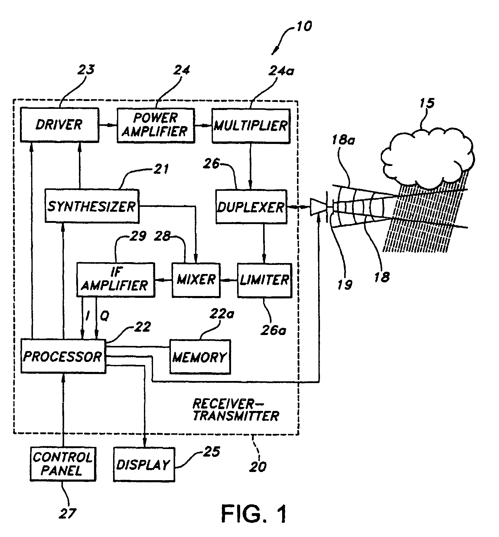
[0055]In a first embodiment shown in FIG. 6, radar return length differentiation is used to separate and edit out shorter returns from the spurious aircraft 35 from longer length weather returns in the weather radar system 10 of FIG. 1. The weather radar system 10 of FIG. 1 may intermix high resolution pulses 61, such as short pulses or compressed long pulses, and long pulses 60 as shown in FIG. 6 while scanning a weather system such as thunderstorm 15. The weather radar system 10 may transmit just the high resolution pulses 61. The receiver-transmitter 20 transmits the high resolution pulses 61 that result in high resolution return pulses 61a from the spurious aircraft 35 and high resolution return pulses 61b from the thunderstorm 15.

[0056]High resolution return pulses 61a from high resolution pulses 61 may not be used for radar display because of low loop gain due to bandwidth but may still be used to identify spurious aircraft 35. The high resolution return pulses 61a from the sp...

second embodiment

[0057]With reference to FIG. 7, system 10 is employed on an airplane 250 to provide transmit pulses 252 across a beam field 254 in accordance with a Return energy 256 from transmit pulses 252 are received by airplane 250. Radar returns 262 are from a lengthy volume target such as weather target 264. Radar return 266 is from a point or point-like target such as point target 268 that is located on the ground. Return 266 is indicative of a ground clutter point target received echo. Return 272 is associated with a weather target 274. System 10 can utilize radar return length differentiation to separate and edit out shorter ground clutter point-like or point targets, such as, target 268, from longer length weather returns, such as, returns 262 and 274.

third embodiment

[0058]In a third embodiment, areas of radar returns from the spurious aircraft 35 that are eliminated from the weather display 25 by using any of the other methods described herein can be tracked into regions where neither the original nor other methods provide detection. The spurious aircraft 35 can continue to be removed by tracking the spurious aircraft 35 into regions where it cannot be detected. As an example in FIG. 8, the antenna 19 on an aircraft 17 points the upper radar beam 30 down to receive return pulses from the weather system 15 and also receives return pulses in the upper radar beam 30 field of view. The processor 22 determines if the return pulses in the upper radar beam 30 field of view are from the spurious aircraft 35 by the size and extent of a vertical gradient return compared to the pulse returns from the weather system 15. The processor 22 identifies the pulses returns as being from the spurious aircraft 35 and accumulates tracking data of the spurious aircra...


PUM


Abstract

A weather radar system is coupled to antenna. The weather radar system includes a processor for generating pulses and for processing return pulses received by the antenna. The processor generates high resolution data from the return pulses. The processor uses the high resolution data to perform high resolution radar analysis including removal of point and/or point-like target returns and reassembles the high resolution data to perform high gain radar analysis at lower resolutions.

Description

CROSS-REFERENCE TO RELATED PATENT APPLICATIONS[0001]The present application is a continuation in part of and claims priority to U.S. Ser. No. 11 / 074,531, now abandoned, filed Mar. 8, 2005 by Daniel L. Woodell, Roy E. Robertson and Charles J. Dickerson entitled, “Removal of Spurious Aircraft Detection on Weather Radar,” and assigned to the Assignee of the present application. The entire contents of U.S. application Ser. No. 11 / 074,531 is herein incorporated by reference. A petition to revive U.S. application Ser. No. 11 / 074,531 is currently pending.BACKGROUND OF THE INVENTION[0002]This application relates to weather radar systems. More particularly, this application relates to weather radar system having improved performance.[0003]Weather radars are known in the art for detecting and displaying severe weather to a crew in an aircraft on a two-dimensional map display showing range, bearing, and intensity of a detected weather system, which may be convective or stratiform in nature. Fl...

Claims


Application Information

Patent Timeline
IPC IPC(8): G01S13/95
CPCG01S7/292G01S13/106G01S13/953G01S13/28Y02A90/10
Inventor WOODELL, DANIEL L.ROBERTSON, ROY E.DICKERSON, CHARLES J.
Owner ROCKWELL COLLINS INC
Why Eureka
Try Eureka