Fiber coupled artificial compound eye

a compound eye and fiber technology, applied in the field of wide angle imaging systems, can solve the problems of large size, limited field of view, long lens life, etc., and achieve the effect of reducing optical aberration and sharpening the imag

Inactive Publication Date: 2008-05-20
SPECTRAL IMAGING LAB
View PDF14 Cites 38 Cited by
  • Summary
  • Abstract
  • Description
  • Claims
  • Application Information

AI Technical Summary

Benefits of technology

[0021]The invention incorporates two components for blocking stray light. The first is a multiple aperture, convex spatial filter array positioned outside the lenslet array to prevent stray light from impinging on the interstices between lenslets. The spatial filter also serves to limit the off-axis height of the lenslet light beam, thereby sharpening the image by reducing optical aberrations. The spatial filter can consist of a light blocking coating formed around the edges of each lenslet, or it can be fabricated as a separate light blocking shell that is bonded to the lenslet array surface. The shell would contain small apertures that are aligned coaxially to the lenslet optical axes. The second component for blocking stray light is a louver baffle consisting of light absorbing honeycomb cells that are many times larger than the diameter of a lenslet. The baffle is attached to the concave side of the inner lenslet array and prevents stray light from exiting the array at large angles to form ghost images.

Problems solved by technology

Single aperture eyes have the advantage of good spatial resolution and good light capture efficiency, but they are disadvantaged by their relatively large size and limited field of view.
Unfortunately the “fish eye lens” distorts the image, making square objects appear round.
The fish eye lens also requires many additional optical elements to control optical aberrations, making the lens expensive, heavy, and long.
Another disadvantage of the conventional single aperture lens is its need for focus adjustment to image objects at different distances.
As with all such auto focusing schemes, it cannot overcome the inherent design limitation of a single aperture lens: objects at different depths of field cannot be brought into focus simultaneously.
However, the flat design attribute limits the field of view to only 21 degrees in this case.
This limits the light collection efficiency considerably, and is why diurnal arthropods require daylight for viewing.
Unfortunately, the design requires a convex shaped detector array of extremely small size to capture the image.
Even if such a detector array could be made, it would be difficult and expensive to manufacture, and its curvature would need to match the curvature of the lenslet array.
The publication by Lee and Szema does not display an image generated by the artificial compound eye they describe, which might be due to problem of finding a proper detector for it.

Method used


Image

  • Fiber coupled artificial compound eye
  • Fiber coupled artificial compound eye
  • Fiber coupled artificial compound eye

Examples


Embodiment Construction

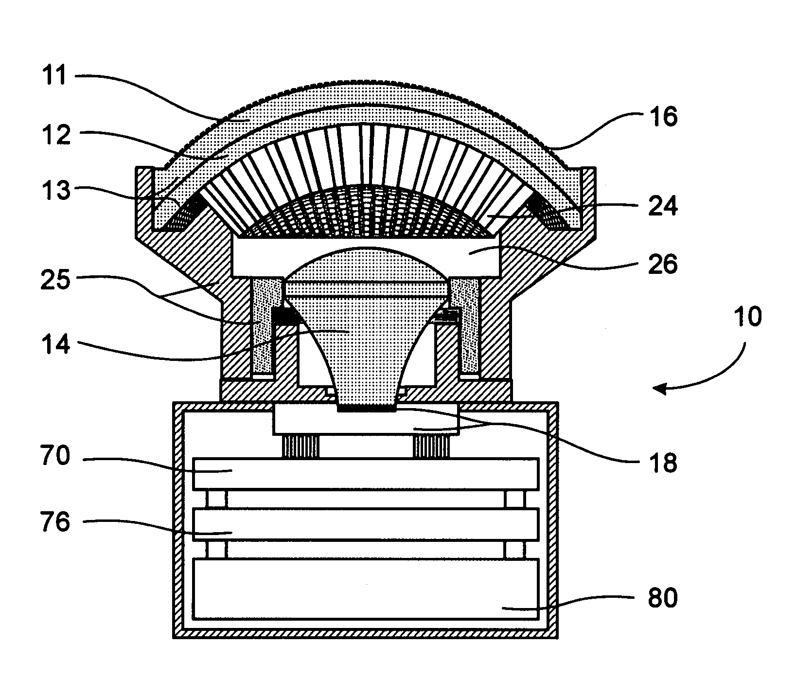
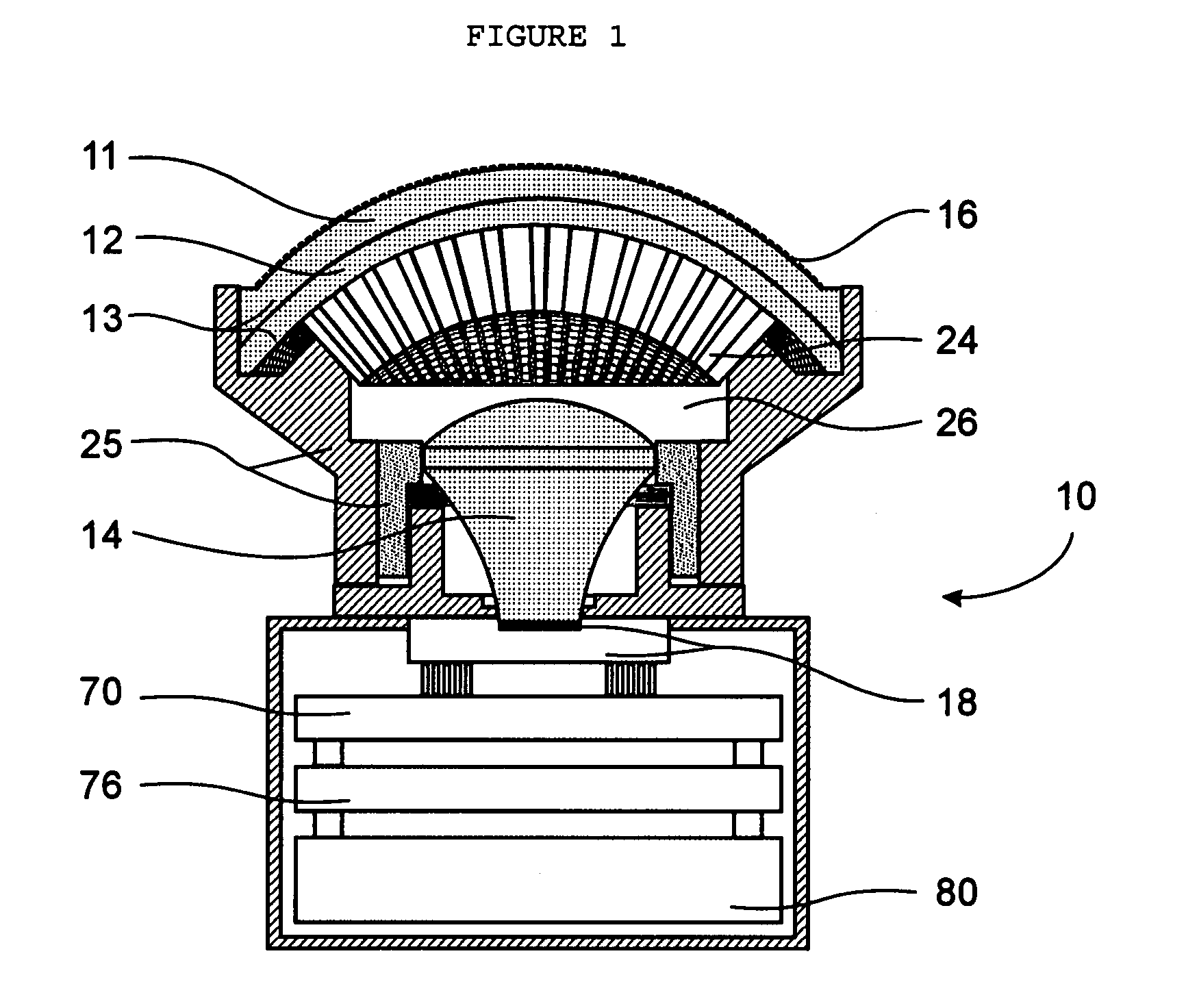
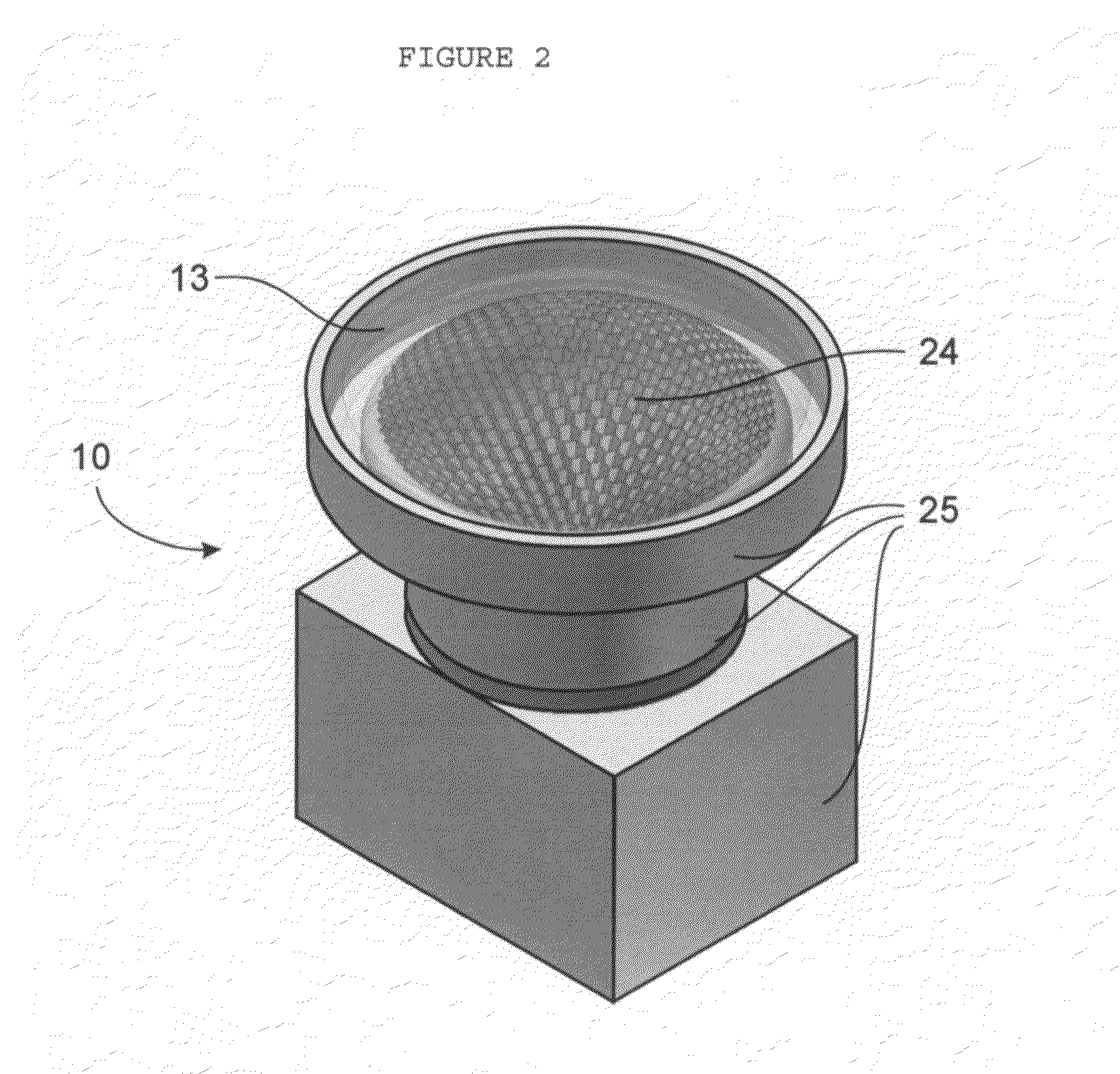
[0040]Referring now to the drawings, FIG. 1 is a cross-sectional view of a superposition array imaging system 10, the preferred embodiment of the fiber coupled artificial compound eye invention. It includes a spatial filter array 16, a lenslet array 13, a louver baffle 24, a fiber optic imaging taper 14, and a mosaic detector array with readout electronics 18, all held rigidly in alignment by a mounting structure 25. The lenslet array 13 is shaped into a positive meniscus form consisting of an outer convex lenslet array 11 and an inner concave lenslet array 12. The spatial filter array 16 is made conformal to the convex lenslet array 11 and the louver baffle 24 is made conformal to the concave lenslet array 12. Between the louver baffle 24 and the fiber optic imaging taper 14 is a clear zone 26 in which can be placed a positive mensicus photo grey glass for controlling light intensity. The photogrey glass and the top of the fiber optic imaging taper 14 must be shaped to conform to t...


PUM


Abstract

A multiple aperture array, wide angle imaging system incorporates compound refractive optics modeled after the eyes of insects. The system channels light through the apertures of a convex spatial filter and a pair of lenslet arrays hot press molded on a positive meniscus form. The lenslets act as afocal Keplerian telescopes to superpose light from hundreds of adjacent channels to a common point on the convex surface of a fiber optic imaging taper. The superposed light from all the channels form a curved, high intensity image that is transformed by the taper into a flat format for readout by a mosaic detector array. The image is upright and distortion free with an infinite depth of field. Ghost images are blocked by a honeycomb louver baffle positioned between the lenslets and the imaging taper. The system is conformable to the geometry of any convex mounting surface, whether spherical, aspherical, or cylindrical.

Description

RELATED APPLICATIONS[0001]The present application is a continuation-in-part application of U.S. provisional patent application Ser. No. 60 / 784,664, filed Mar. 22, 2006, for FIBER COUPLED ARTIFICAL COMPOUND EYE, by Francis M. Reininger, included by reference herein and for which benefit of the priority date is hereby claimed.FIELD OF THE INVENTION[0002]The present invention relates to wide angle imaging systems and, more particularly, to multiple aperture wide angle imaging systems that have curved lenslet arrays.BACKGROUND OF THE INVENTION[0003]Conventional camera systems are modeled after the single aperture eyes of vertebrates. Single aperture eyes have the advantage of good spatial resolution and good light capture efficiency, but they are disadvantaged by their relatively large size and limited field of view. Vertebrates evolved to overcome the field of view limitation by gimbaling the eye in its socket. Camera developers have overcome the field of view limitation by inventing w...

Claims


Application Information

Patent Timeline
Patent Type & Authority Patents(United States)
IPC IPC(8): G02B6/26
CPCG02B6/06B33Y80/00
Inventor REININGER, FRANCIS MARK
Owner SPECTRAL IMAGING LAB
Why Eureka
Try Eureka