Projection system and projector with light-shielding mask
a projection system and projector technology, applied in the field of projection systems and projectors, can solve problems such as peripheral components, damage to the lens unit, and damage at a site having a high temperature, and achieve the effects of reducing the cost of the lens, and restrainting the temperature ris
- Summary
- Abstract
- Description
- Claims
- Application Information
AI Technical Summary
Benefits of technology
Problems solved by technology
Method used
Image
Examples
embodiment 1
Overall Configuration
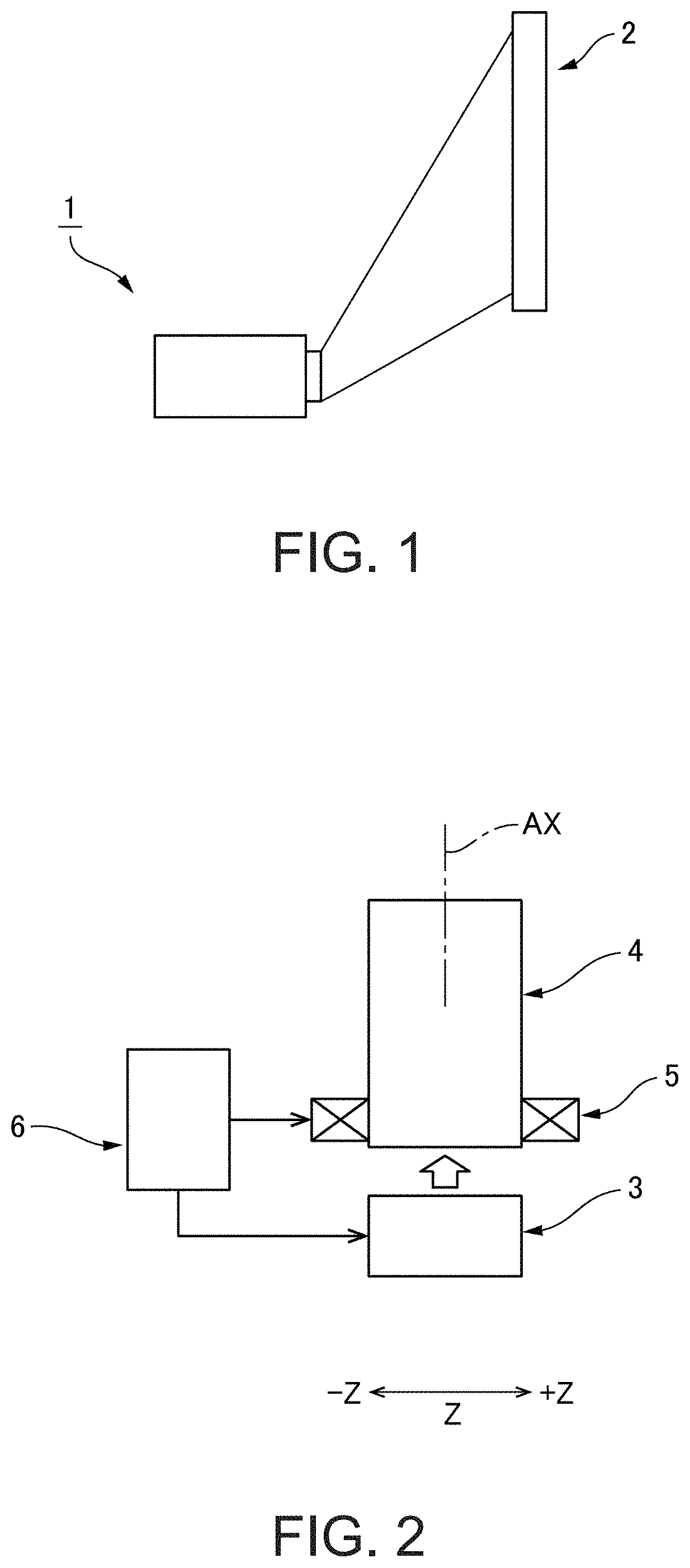
[0027]FIG. 1 is an explanatory view schematically showing the state of use of a projector 1 according to Embodiment 1 to which the invention is applied. FIG. 2 is an explanatory view schematically showing a schematic configuration of the projector 1 according to Embodiment 1. As shown in FIG. 1, the projector 1 according to Embodiment 1 projects image light toward a screen 2. The projector 1 is a short throw projector which generates wide-angled image light, using a lens with a wide angle of view or the like, and projects the generated image light onto the screen at a short projection distance. The image light emitted from the projector 1 can display an image with little distortion even if the image light enters at a steep angle on the screen 2.
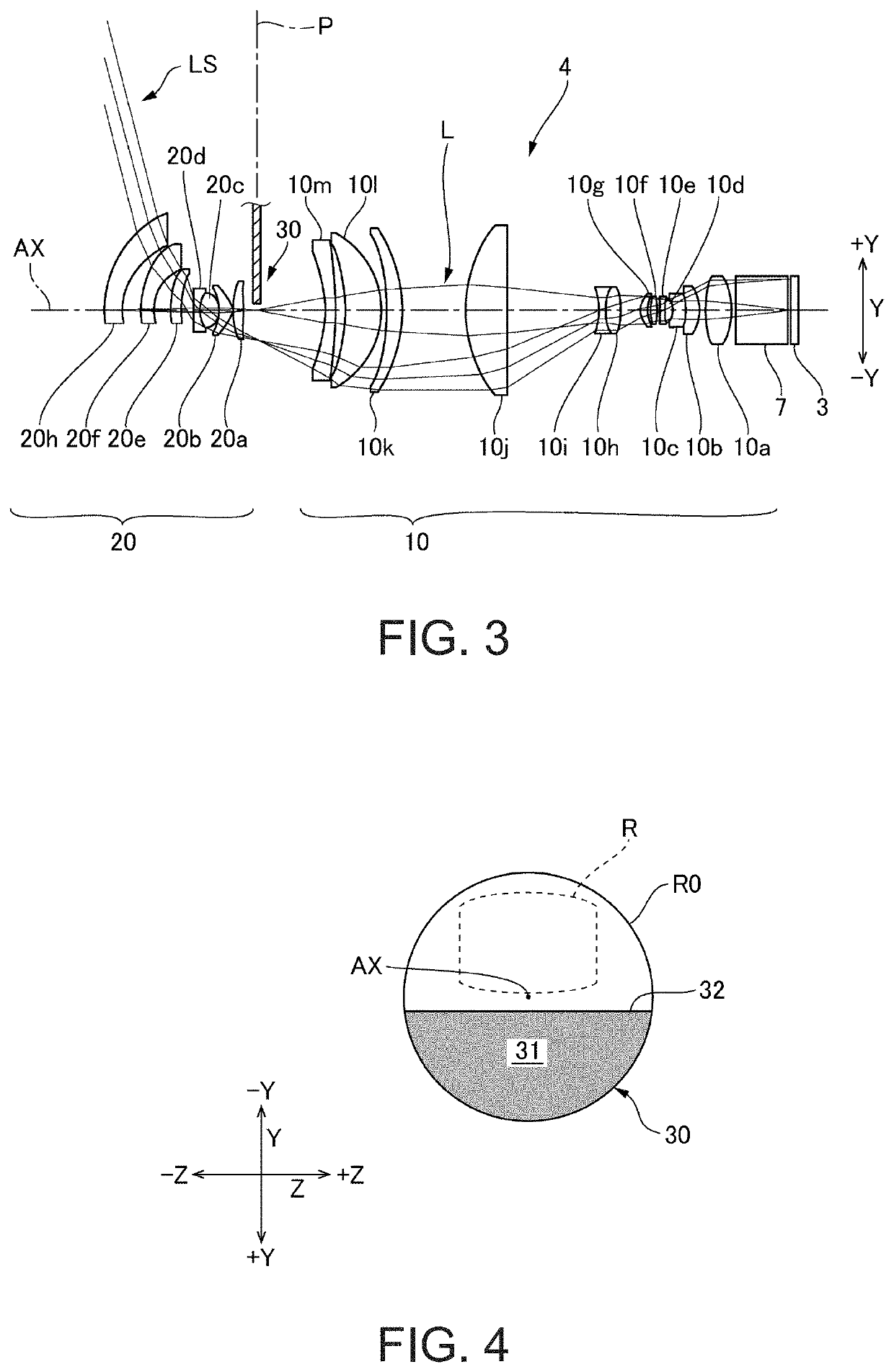
[0028]As shown in FIG. 2, the projector 1 has an image generation unit 3, a projection system 4, a lens shift mechanism 5, and a control unit 6. In the projector 1, the projection system 4 is removable. These mechanisms a...
modification 1
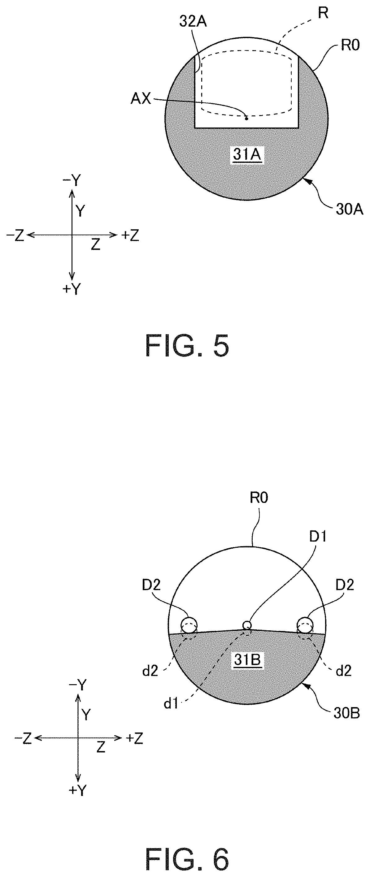
[0047]FIG. 5 is an explanatory view of a light-shielding area 31A by a light-shielding mask 30A of Modification 1. In Embodiment 1, only the area in the +Y direction from the intermediate image R is shielded from light, whereas the light-shielding area 31A by the light-shielding mask 30A in Modification 1 is an area covering three directions, that is, the +Y direction side of the intermediate image R (that is, the side opposite to the side to which the intermediate image R is shifted from the center of the effective image forming area R0), and both sides in the second direction Z of the intermediate image R (that is, both sides in the second direction Z orthogonal to the direction of the optical axis AX and the first direction Y), within the range of the effective image forming area R0. The light-shielding area 31A is marked off by a boundary 32A in a recessed shape that is recessed in the +Y direction. Thus, not only unwanted light in the direction of image height but also unwanted...
embodiment 2
[0052]FIG. 9 is a cross-sectional configuration view of a projection system 104 according to Embodiment 2. Hereinafter, only the differences between the projection system 104 of Embodiment 2 and that of Embodiment 1 will be described. While the optical path of the projection system 4 of Embodiment 1 is not bent, the projection system 104 of Embodiment 2 is provided with flat-surface mirrors 8 and 9 in the course of its optical path. The mirrors 8 and 9 change the direction of the optical path by 90 degrees each. Therefore, the exiting direction of the image light is changed by 180 degrees. Also, while the above configuration has flat-surface mirrors for changing direction, curved-surface lenses may be employed.
[0053]The projection system 104 of Embodiment 2 forms an intermediate image at a halfway point, as in Embodiment 1. The image forming position P of the intermediate image is situated to the exiting side of the mirrors 8 and 9. However, the image forming position P of the inter...
PUM
 Abstract
Description
Claims
Application Information
 - R&D
- Intellectual Property
- Life Sciences
- Materials
- Tech Scout
- Unparalleled Data Quality
- Higher Quality Content
- 60% Fewer Hallucinations
Browse by: Latest US Patents, China's latest patents, Technical Efficacy Thesaurus, Application Domain, Technology Topic, Popular Technical Reports.
© 2025 PatSnap. All rights reserved.Legal|Privacy policy|Modern Slavery Act Transparency Statement|Sitemap|About US| Contact US: help@patsnap.com


