System and method for gas flow verification

a gas flow and verification system technology, applied in the direction of liquid/fluent solid measurement, machines/engines, instruments, etc., can solve the problem that the mfc device is typically not capable of matching the tight tolerance level of the mfc design specification, and the mfc device is a complex and sensitive instrumen

Active Publication Date: 2008-05-20
LAM RES CORP
View PDF8 Cites 332 Cited by
  • Summary
  • Abstract
  • Description
  • Claims
  • Application Information

AI Technical Summary

Problems solved by technology

It should be appreciated that the MFC device is a complex and sensitive instrument having a real-world gas flow rate control accuracy that is dependent upon many factors.
Thus, the MFC verification during manufacture may not bound the environmental conditions to which the MFC will be exposed during a real-world implementation.
Furthermore, after the MFC device is shipped to the end-user and installed in the end-user's system, a potential exists for the MFC device to be out of tolerance with respect to its design specification.
However, the end-user's equipment for verifying the gas flow rate control accuracy of the MFC device is typically not capable of matching the tight tolerance levels of the MFC design specification.

Method used


Image

  • System and method for gas flow verification
  • System and method for gas flow verification
  • System and method for gas flow verification

Examples


Embodiment Construction

[0016]In the following description, numerous specific details are set forth in order to provide a thorough understanding of the present invention. It will be apparent, however, to one skilled in the art that the present invention may be practiced without some or all of these specific details. In other instances, well known process operations have not been described in detail in order not to unnecessarily obscure the present invention.

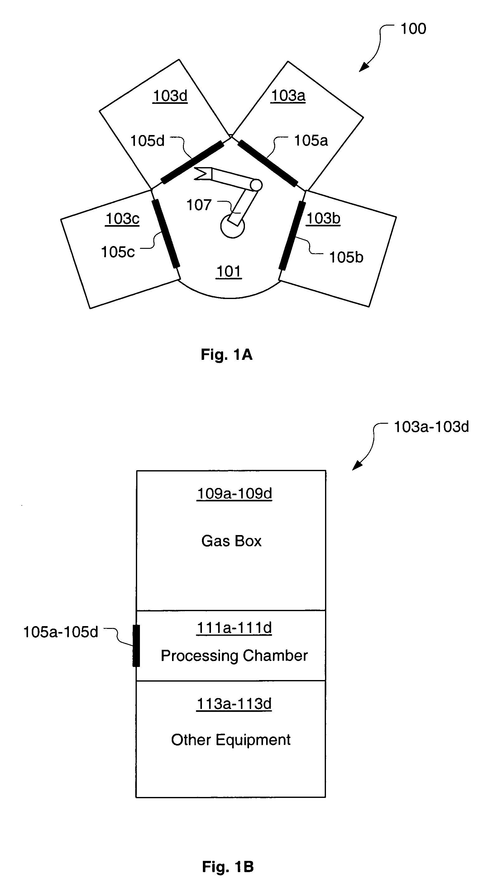
[0017]FIG. 1A is an illustration showing a top view of a central cluster tool platform (“tool platform”) 100 including multiple process modules 103a-103d, in accordance with one embodiment of the present invention. The tool platform 100 includes a central area 101 from which an access 105a-105d of each process module 103a-103d is accessible. A wafer transfer mechanism 107 is disposed within the central area 101, such that a wafer can be transferred to or from each process module 103a-103d. In one embodiment, the transfer mechanism 107 is defined as a ro...


PUM


Abstract

A gas flow rate verification apparatus is provided for shared use in a multiple tool semiconductor processing platform. The gas flow rate verification apparatus is defined to measure a pressure rate of rise and temperature within a test volume for determination of a corresponding gas flow rate. The apparatus includes first and second volumes, wherein the second volume is larger than the first volume. The apparatus also includes first and second pressure measurement devices, wherein the second pressure measurement device is capable of measuring higher pressures. Based on the target gas flow rate to be measured, either the first or second volume can be selected as the test volume, and either the first or second pressure measurement device can be selected to measure the pressure in the test volume. Configurability of the apparatus enables accurate measurement of gas flow rates over a broad range and in an time efficient manner.

Description

BACKGROUND OF THE INVENTION[0001]A number of modern semiconductor wafer fabrication processes require a process gas to be supplied in a carefully controlled manner to a reaction chamber, wherein the process gas is used to support or effect processing of the semiconductor wafer. For example, in a plasma etch process, a process gas is supplied to an etching chamber, wherein the process gas is converted to a plasma for etching materials present on the surface of the wafer. In most cases, the semiconductor wafer fabrication processes require the process gas supply to be carefully controlled. More specifically, a flow rate of the process gas to the reaction chamber needs to be maintained within a range defined by a recipe of the fabrication process. The process gas flow rate is commonly controlled by a mass flow controller (MFC) upstream from the reaction chamber. Thus, the accuracy at which the process gas flow rate can be controlled is generally dictated by the accuracy of the MFC thro...

Claims


Application Information

Patent Timeline
Patent Type & Authority Patents(United States)
IPC IPC(8): G01F1/00G01F7/00
CPCG01F1/34G01F7/005G01F25/0053G01F22/02G01F25/0038G01F17/00G01F25/17G01F25/15
Inventor WONG, VERNONMEINCCKE, RICHARD J.
Owner LAM RES CORP
Why Eureka
Try Eureka