Shock absorbing device for moving body

a technology of moving body and shock absorption device, which is applied in the direction of shock absorbers, wing accessories, manufacturing tools, etc., can solve the problems of difficult to set the dynamic range of damping force over a wide operating range, affecting the operability of the device, and insufficient damping force at high speed, so as to achieve the effect of preventing the flow of viscous fluid through the gap, preventing the device from being damaged, and maintaining the fluid resistance of the viscous fluid

Active Publication Date: 2008-05-27
NIFCO INC
View PDF34 Cites 13 Cited by
  • Summary
  • Abstract
  • Description
  • Claims
  • Application Information

AI Technical Summary

Benefits of technology

[0012]With this arrangement, when the damper is in a state in which the movement speed of the piston rod is comparatively low, the gap between the inner member and the outer member is relatively wide and is maintained by the bias of the compression coil spring. Under these conditions, the fluid resistance of the viscous fluid is kept sufficiently low such that the operability of the device is not impaired.
[0013]When the speed of the piston rod exceeds a predetermined value and the resistance force of the viscous fluid acting on the outer member rises above the biasing force of the compression coil spring, the coil spring contracts and the inner member moves into the outer member. In accordance with this relative movement, the gap between the inner member and the outer member is reduced and the resistance to the flow of the viscous fluid passing through that gap, is further increased. A greater damping force is therefore generated.
[0014]Accordingly, in accordance with this embodiment of the present invention, a highly beneficial effect can be achieved wherein the ratio of the change of damping force with respect to the change of piston speed, is increased and the applicable range of the damper is expanded.
[0015]Therefore, in accordance with this embodiment of The shock absorbing device, the impact of the moving body can be attenuated, and the generation of unpleasant noise, and the like, can be reduced.

Problems solved by technology

However, setting of the damping force is accomplished exclusively by the sizing of the aperture of the orifice provided in the piston, and there is a shortcoming that when the operating force at low speed is set appropriately, the damping force at high speed becomes rather insufficient, and conversely, when the damping force at high speed is set appropriately, the operability at low speed is impeded.
Accordingly, it has been difficult to set the dynamic range of the damping force over a wide operating range.

Method used


Image

  • Shock absorbing device for moving body
  • Shock absorbing device for moving body
  • Shock absorbing device for moving body

Examples


Embodiment Construction

[0029]The embodiments of the present invention will now be explained in detail with reference to the appended drawings.

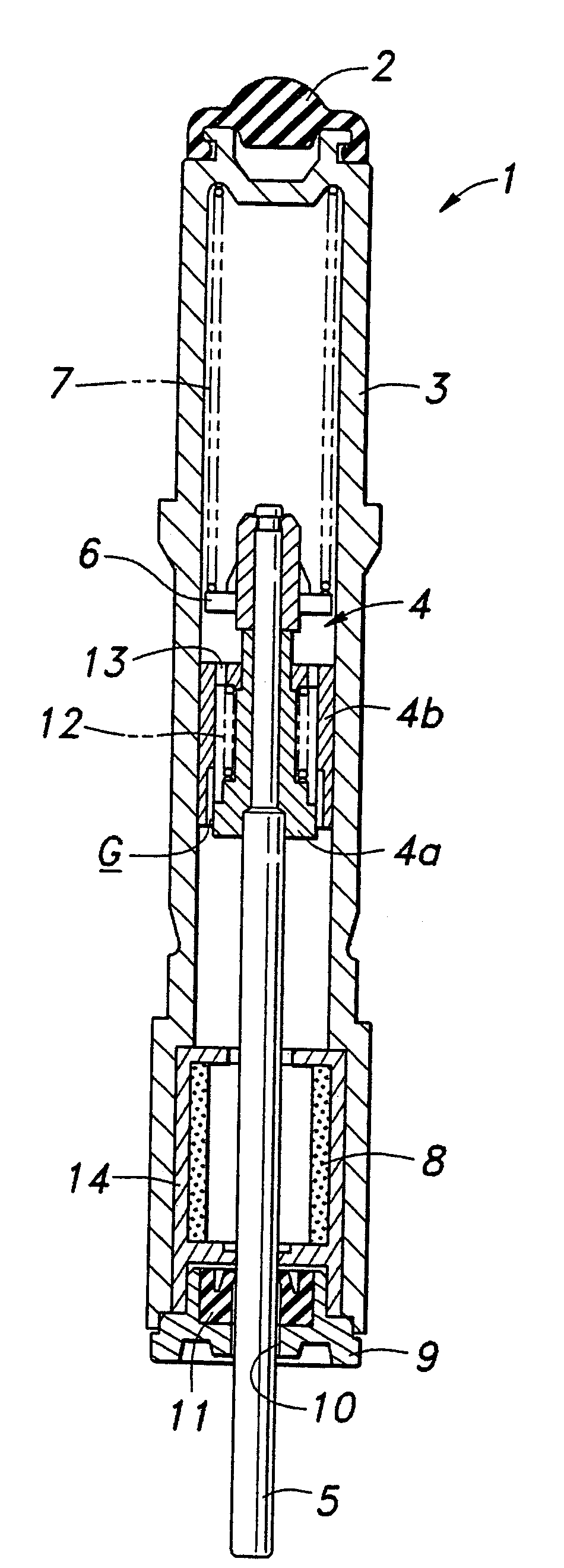
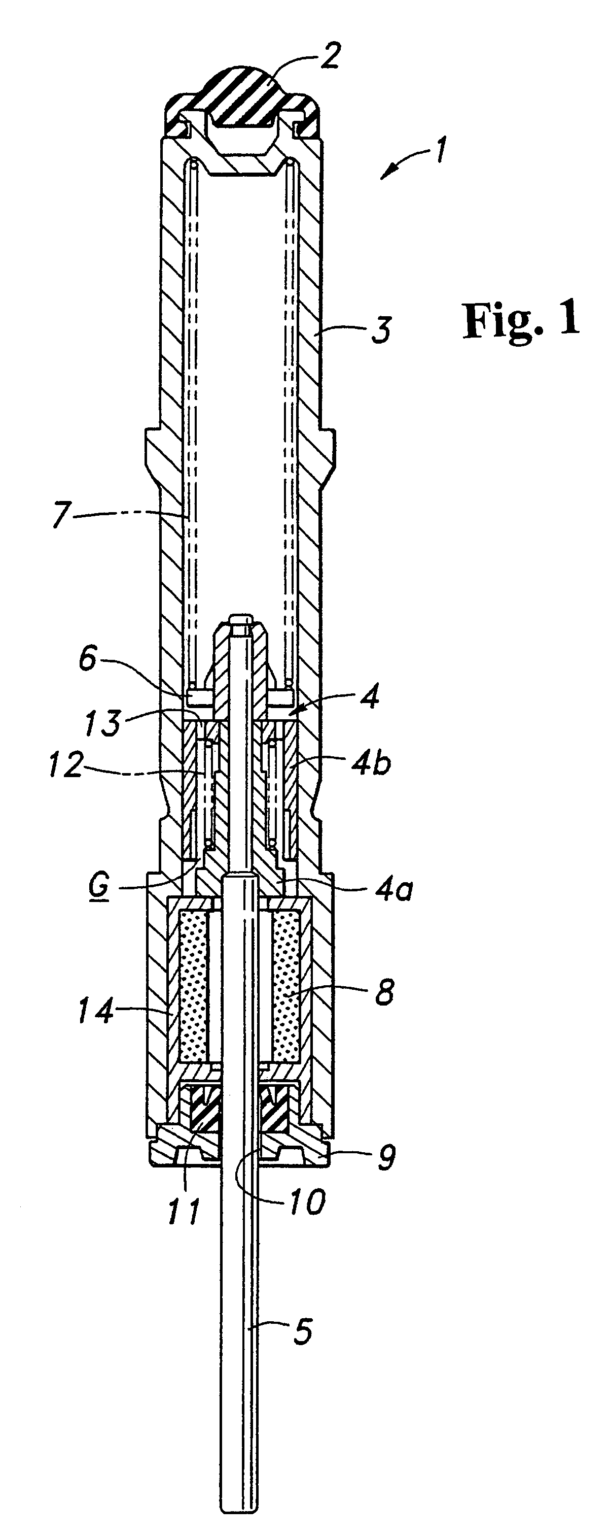
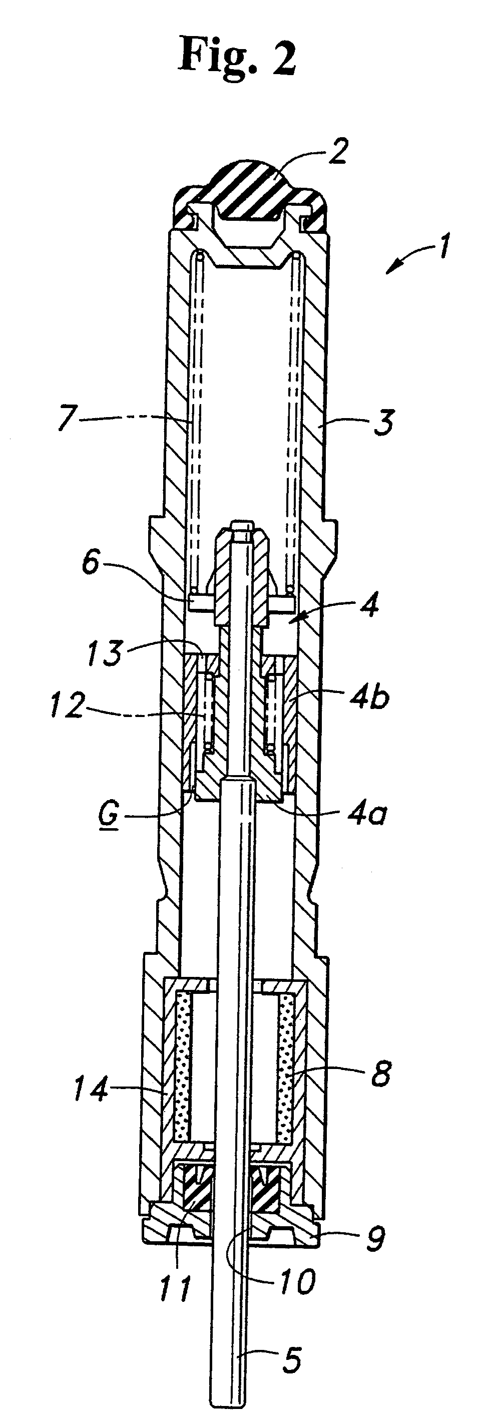
[0030]FIG. 1 is a sectional view of a damper according to an embodiment of the present invention. This damper 1 includes a cylinder 3 wherein one end is closed and a cushion rubber 2 is attached thereto. A piston 4 is slide-coupled inside the cylinder 3, and a piston rod 5 is connected to the piston 4. A first compression coil spring 7 is disposed between a spring retainer 6 provided on the inboard end of the piston rod 5 and the closed end of the cylinder 3. An accumulator 8 is provided within the cylinder in the manner shown. A cap 9 closes the open end of the cylinder in a manner wherein the piston rod 5 extends through a hole 10 in the cap 9 via an oil seal 11 and extends out of the cylinder 3. The cylinder 3 is filled with a silicon oil having a suitable viscosity.

[0031]The piston 4 comprises an inner member 4a which is integral (fixedly connected) with the inb...


PUM


Abstract

A shock absorbing device uses a damper including a cylinder enclosing a viscous fluid; a piston rod; and a piston dividing the interior of the cylinder in two axially separated parts. The piston is connected to the piston rod and has an orifice communicating the two parts. The piston includes an inner member integrally connected with the piston rod, and an outer member disposed about an outer perimeter of the inner member and configured to be axially movable with respect to the inner member. The inner and outer members are configured to define a gap therebetween through which the viscous fluid can flow, and to be biased away from each other by a spring disposed therebetween. The inner and outer members are arranged so that the gap is reduced as the amount that the inner member protrudes into the outer member increases, to thereby define a variable orifice.

Description

CROSS-REFERENCE TO RELATED APPLICATION[0001]This is a continuation-in-part application of Ser. No. 11 / 009,043 filed on Dec. 13, 2004.BACKGROUND OF THE INVENTION AND RELATED ART STATEMENT[0002]The present invention relates to a shock absorbing device for arresting the movement of a moving body and more specifically to shock absorbing device which uses a damper having a cylinder that slidingly receives a piston having an orifice and which is filled with a viscous fluid.[0003]It is known that, in order to prevent the generation of impact noise which tends to be produced when a structure such as a cabinet door, or the like, is closed rapidly, a damper, which reduces the speed of the speed at which the door closes, can be disposed on a door stop of the cabinet.[0004]As a damper for generating such damping force, there is known one that has a cylinder enclosing a viscous fluid, a piston which divides the interior of the cylinder into two axially separated sections and which has an orifice...

Claims


Application Information

Patent Timeline
Patent Type & Authority Patents(United States)
IPC IPC(8): F16F9/50F16F9/34F16F9/512F16F9/53
CPCF16F9/3405F16F9/5126E05F5/10E05Y2201/21E05Y2201/256E05Y2201/264E05Y2900/538Y10T16/27E05Y2900/20E05Y2900/148E05Y2900/30E05Y2900/132Y10T16/276E05Y2900/614
Inventor TOMIJI, KATSUYASUTSUCHIYA, TAKEFUMI
Owner NIFCO INC
Why Eureka
Try Eureka