Arched soil nail wall

a three-dimensional, soil nail wall technology, applied in the direction of shaft equipment, shaft lining, other domestic articles, etc., can solve the problems of difficult installation of steel-reinforced shotcrete soil nail wall facings, inconvenient installation of soil nail wall under certain conditions, and freeze of shotcrete, etc., to achieve short standup time, minimize ground movement, and low construction cost

Inactive Publication Date: 2008-05-27
SHEET PILE LLC
View PDF28 Cites 24 Cited by
  • Summary
  • Abstract
  • Description
  • Claims
  • Application Information

AI Technical Summary

Benefits of technology

[0017]It is, therefore, an object of the present invention to provide a three-dimensional soil nail wall that is inexpensive to construct, requires a short standup time, and minimized ground movement.
[0018]It is another object of the present invention to reduce the time required for construction of soil nail walls by eliminating the time required for assembly of a steel reinforcing system and curing of shotcrete.
[0019]It is yet another object of the present invention to allow construction of soil nail walls during cold weather, to reduce problems related to ice formation, and to eliminate shotcrete cracking problems.

Problems solved by technology

Shotcrete facing systems present numerous problems which make them unsuitable for installation under certain conditions.
Steel-reinforced shotcrete soil nail wall facings are difficult to install in cold weather.
The air used to propel the shotcrete onto the slope expands at the applicator nozzle and may cause the shotcrete to freeze if the ambient air temperature is below about 40° F. In addition, ground water can collect between the soil face and the shotcrete and lead to fracturing of the shotcrete around the soil nail heads.
Shotcrete also provides a very crude finish thereby making the CSN wall unaesthetic.
However, the labor and materials required to provide such finishes are expensive.
This method of supporting the fascia wall is not desirable in that it is indirectly supported in the primary wall structure, increases the cost of wall construction, and provides another mechanism that could lead to wall failure.
The wall's appearance may remain marred even after repairs are performed.
Reinforced shotcrete facings must bend to restrain soil from moving further, but in actuality, these facings present little bending strength and tend to readily crack.
As tension develops in the reinforcing steel, the shotcrete facing bulges outward resulting in the formation of cracks.
Steep vertical slopes, such as those located on the west coast of the United States, can become unstable and collapse following periods of heavy rain.
Seepage forces due to groundwater that flows through the soil and down to lower elevations can lead to a loss of slope strength.
CSN walls are largely ineffective in these areas because they are not aesthetically pleasing.
The passive support offered by CSN walls does not address the larger problem of preventing ground movement.
Thus, a real and unfulfilled need exists for an active retaining wall system that takes advantage of the soil arching phenomenon and does not possess the above-described problems which are inherent of conventional passive systems.

Method used


Image

  • Arched soil nail wall
  • Arched soil nail wall
  • Arched soil nail wall

Examples


Embodiment Construction

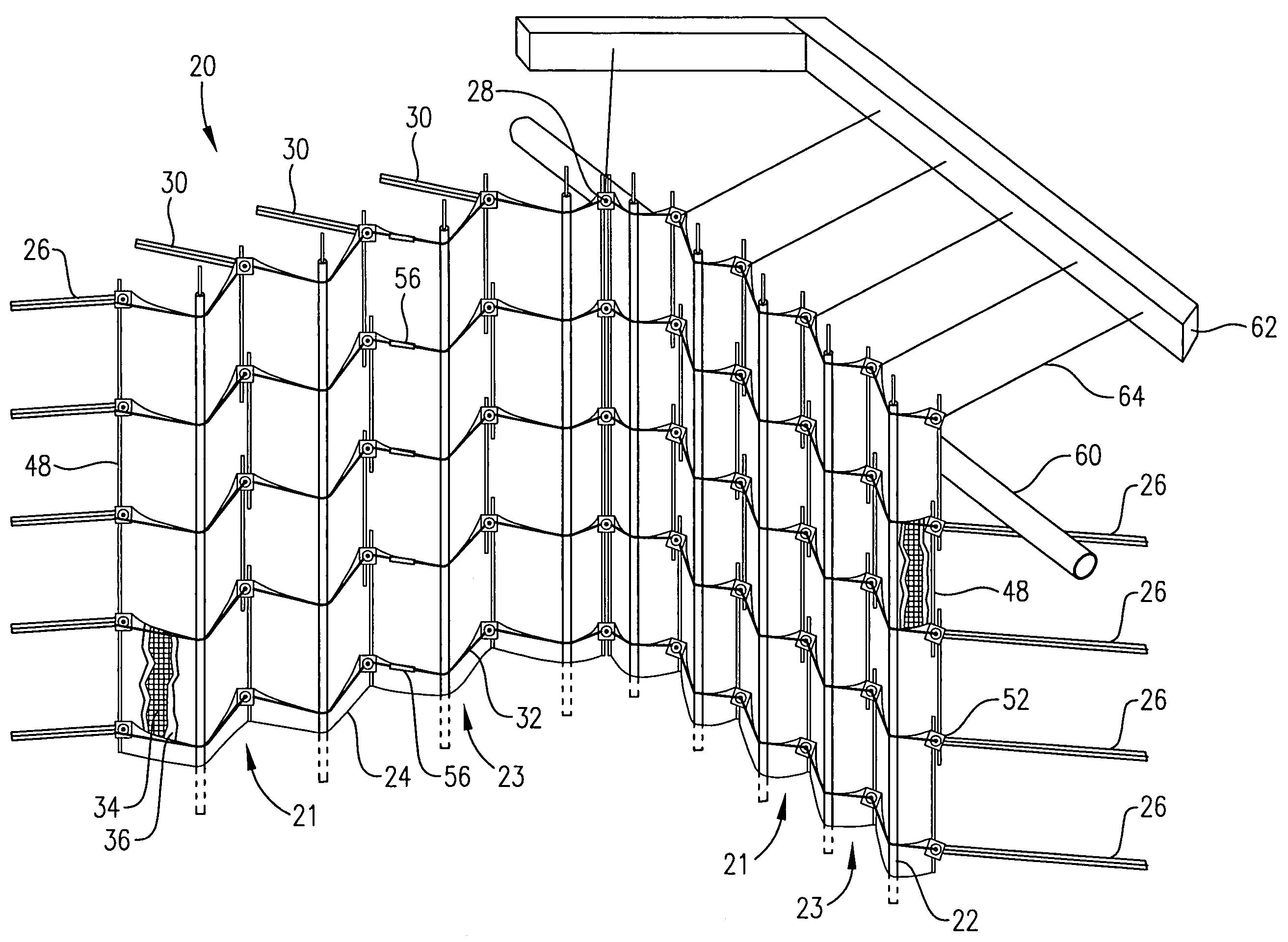
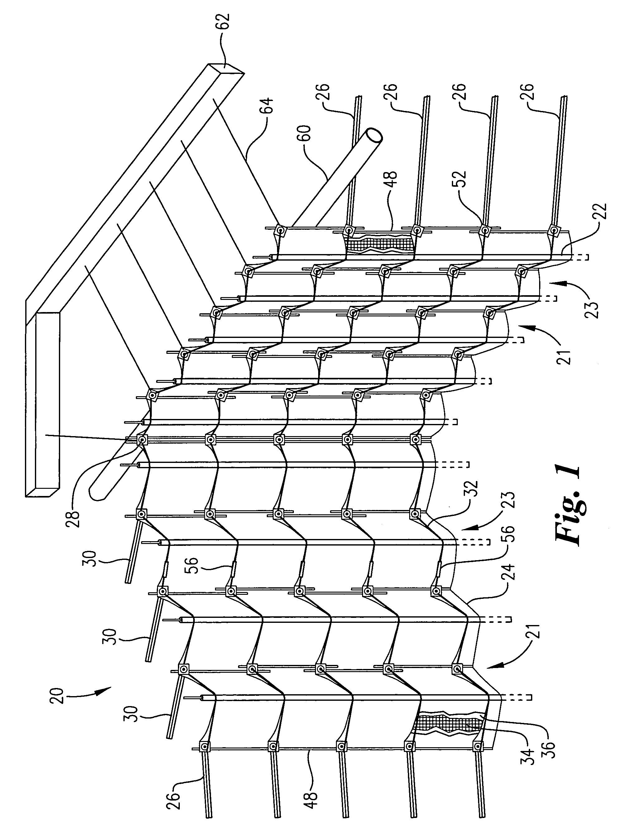
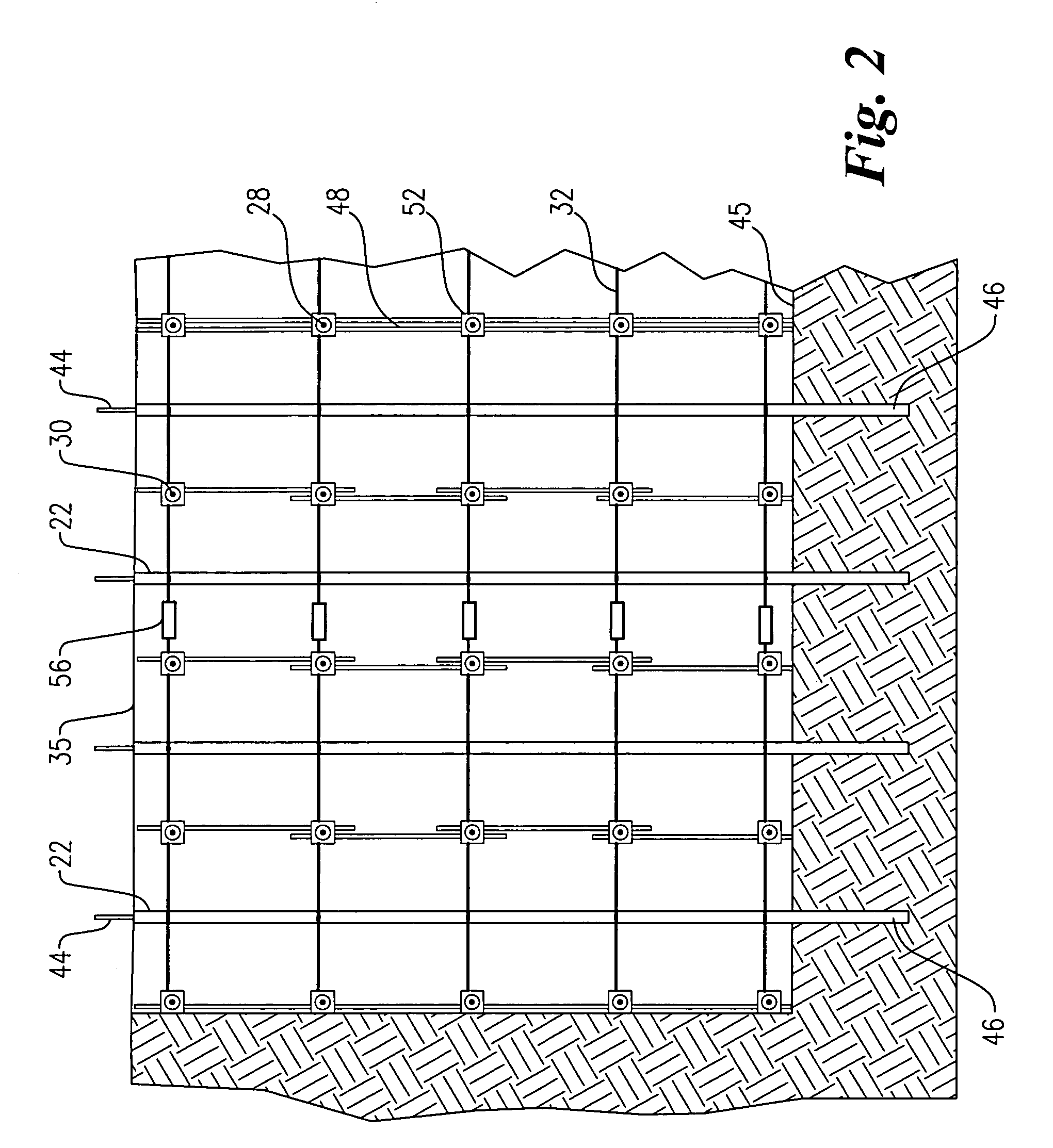
[0045]Referring initially to FIG. 1, a soil nail wall system 20 is depicted supporting a rectangular excavation, the inside corner of wall 20 being in the center of the view. An upright face 24 of the excavation presents a number of recessed areas 21 formed therein. Recessed areas 21 cause face 24 to assume an undulating, three-dimensional profile comprising alternating, vertically-extending recesses 21 and protrusions 23.

[0046]In this particular embodiment, wall 20 comprises a plurality of vertically-installed piles 22 spaced across upright face 24 of the rectangular excavation. Wall system 20 also includes a plurality of conventional soil nails 26-30 installed in recessed areas 21. A plurality of reinforcing cables 32, also referred to herein as wire rope wales, extend across upright face 24 and are secured to soil nails 26-30. A plurality of sheets of a web 34 comprising a mesh of pliable material (also referred to herein as sheets of geogrid) and a geotextile fabric 36 cover sub...


PUM


Abstract

Three-dimensional soil nail walls employing geosynthetic materials and methods of installation thereof. The soil nail walls are suitable for supporting an upright face of earth and comprise tensioned geosynthetic material held up against the face.

Description

RELATED APPLICATION[0001]This application claims the priority benefit of U.S. Provisional Patent Application Ser. No. 60 / 643,253, filed Jan. 12, 2005, which is incorporated by reference herein.BACKGROUND OF THE INVENTION[0002]1. Field of the Invention[0003]The present invention relates generally to the construction of three-dimensional soil nail walls comprising geosynthetic material facing systems, and optionally steel wire rope wales and soldier piles. A three-dimensional face wall including alternating, vertically-extending recessed and protruding portions is excavated that has a serpentine, ribbon-like arrangement. The geosynthetic materials are connected to the soil nails and then tensioned and drawn toward the slope so as to apply pressure to the soil face thereby creating zones of compressed soil within the slope.[0004]2. Description of the Prior Art[0005]Retaining wall systems are essential components of many excavation projects. Conventional soil nail (CSN) walls are common...

Claims


Application Information

Patent Timeline
Patent Type & Authority Patents(United States)
IPC IPC(8): E02D17/20B21F27/08E02D5/80E04H17/04
CPCE02D29/0233
Inventor CAMMACK, CHARLES H.
Owner SHEET PILE LLC
Why Eureka
Try Eureka