
System and method for detecting and eliminating IP spoofing in a data transmission network

a data transmission network and spoofing technology, applied in the field of data network control systems, can solve problems such as the high probability that the system is dealing with an invalid pack

Inactive Publication Date: 2008-05-27
TREND MICRO INC
View PDF45 Cites 263 Cited by
  • Summary
  • Abstract
  • Description
  • Claims
  • Application Information

AI Technical Summary

Benefits of technology

[0013]One embodiment of this invention includes a system which implements a three tiered architecture where the database runs on one computer, or across multiple computers, and the kernel and all of its intelligence runs on a separate computer while the applications and management tools run on other computer(s). The system is designed to monitor every TCP / IP packet directed toward a company and to keep track of each packet from each IP address, including all of the bytes of information associated with each packet. The goal of the system and method is to prevent flooding which is defined as a threshold above which data throughput or packet throughput must not go.
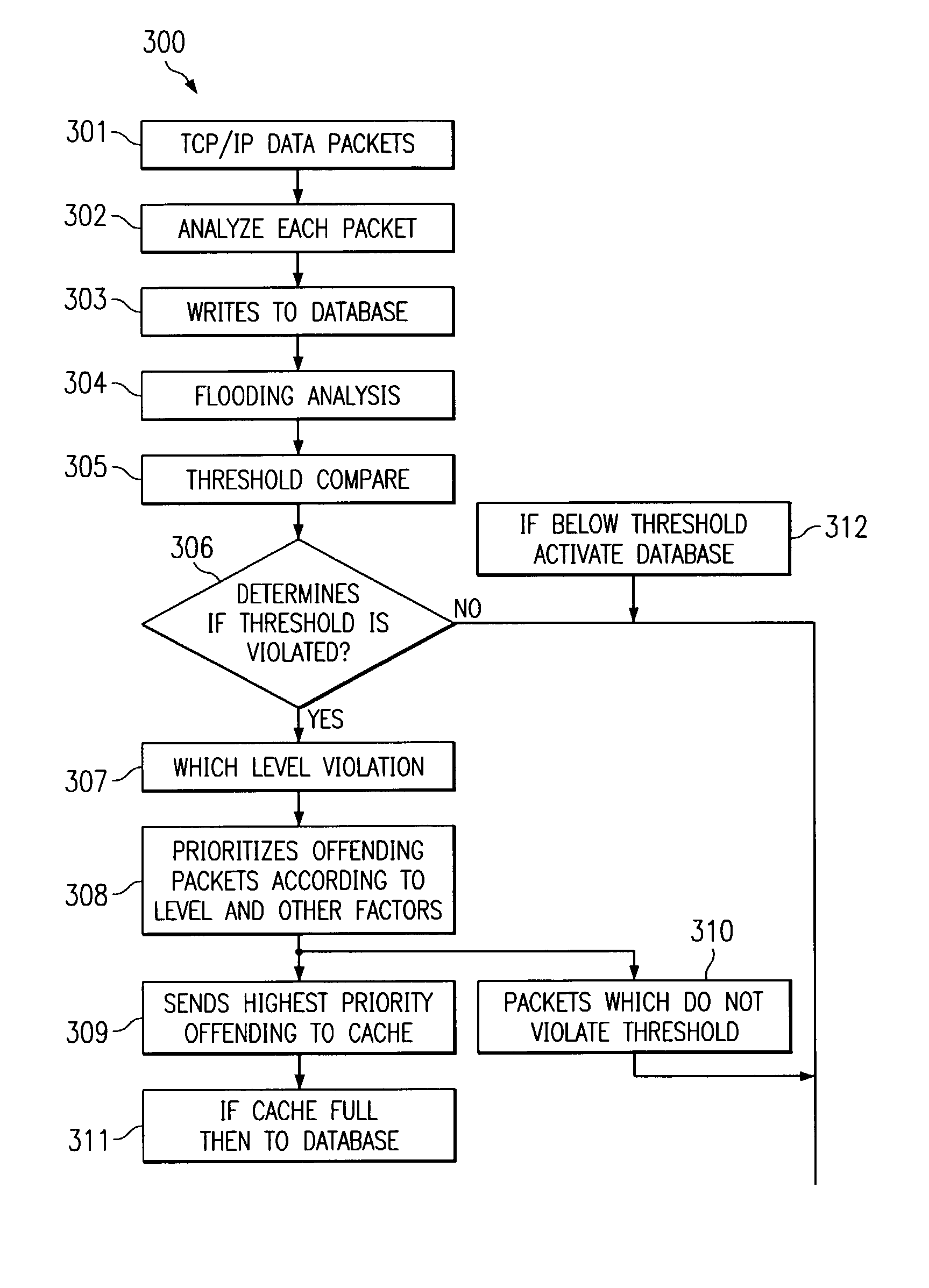
[0015]Generally, when it comes to flooding, there are four (or more or less) threshold levels which exist which are percentages of the total maximum band-width of the network. The thresholds can be for example 20, 30, or 40 percent of maximum. If the traffic flow is under the lowest threshold, everything runs smoothly. Once the number of arriving packets and / or accumulated bytes violate a threshold, the system begins, automatically, the process of choking or holding certain packets and sends alarms and notifications to predetermined lists of people. If higher thresholds are violated then more and more severe action is taken, i.e., more and more packet(s) are prevented from flowing through the system and additional alarms and notifications are sent.

Problems solved by technology

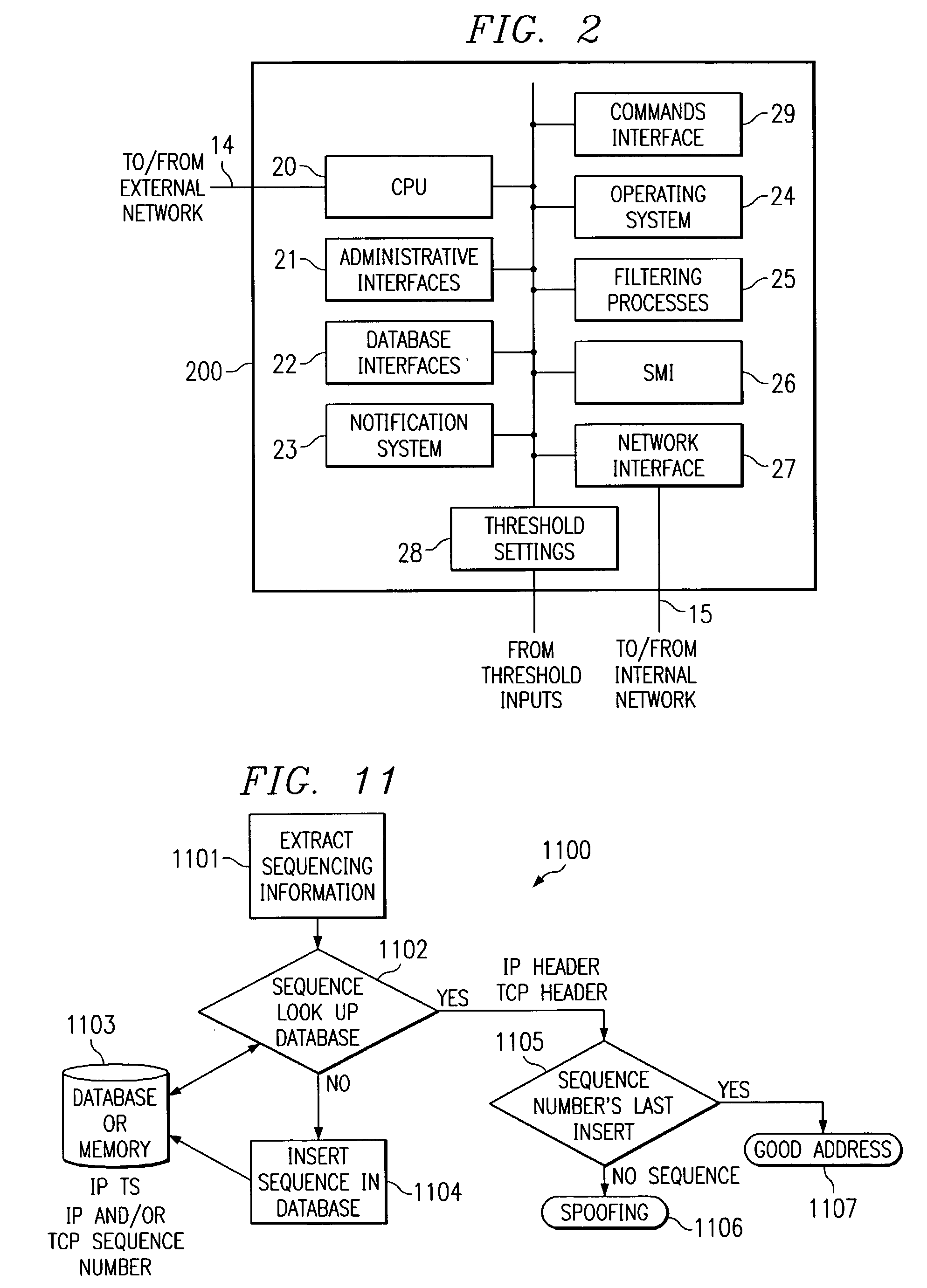
If suddenly, the expected sequence of numbers follows some unexpected sequence, there again is a high probability that the system is dealing with an invalid packet.

Method used


Image

  • System and method for detecting and eliminating IP spoofing in a data transmission network
  • System and method for detecting and eliminating IP spoofing in a data transmission network
  • System and method for detecting and eliminating IP spoofing in a data transmission network

Examples


Embodiment Construction

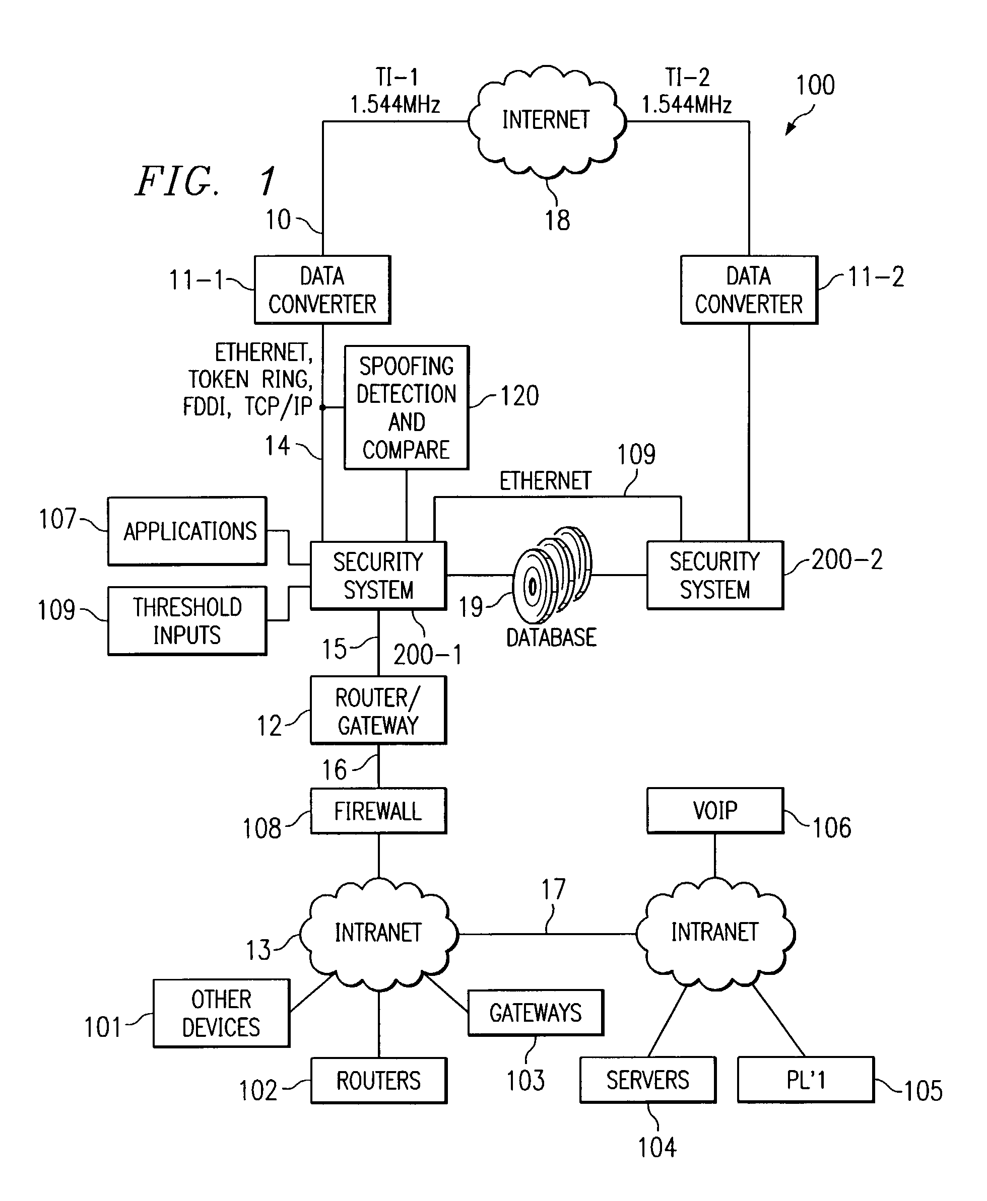
[0026]Turning now to FIG. 1, as packets come from internet 18 (or any source), they travel to data converter 11-1 (11-2) through line 10, which could be a T1, T3, OC48 or any other communication media. Data converter 11-1 can be several data converters which take the data packets off the line and convert that data to an “internal” protocol, such as token ring, FDDI, TCP / IP or other protocol desired by an enterprise. These packets then pass to security system 200-1 one medium 14. When the packets arrive at security system 200-1, each packet will be analyzed, as will be discussed hereinafter. Only those medium packets which make their way through security system 200-1 are delivered to router 12 over 15. Router 12 could be a combination router / gateway or, in fact, router 12 and / or firewall 108 could be built directly into security system 200-1 if so desired.

[0027]If desired, a spoofing detector and control 120 can be added to applications 107 or could be stand alone (as shown) and can ...


PUM


Abstract

A traffic management system sniffs data arriving at any point in a system. The sniffer operates to extract certain data from each address. This data could be, for example, the IP address data and the physical address data. The extracted data is then used to access different data bases to determine if matches occur. Time stamps, sequencing and other parameters of each piece of data entering a system are used to control data access.

Description

CROSS-REFERENCE TO RELATED APPLICATIONS[0001]This application is a Continuation-in-Part of U.S. patent application Ser. No. 09 / 875,319, filed Jun. 6, 2001, now U.S. Pat. No. 6,930,978 which is a Continuation-in-Part of U.S. patent application Ser. No. 09 / 572,112 filed May 17, 2000, now U.S. Pat. No. 7,058,976 and entitled “Intelligent Feedback Loop Process Control System,” both of which are hereby incorporated herein by reference.BACKGROUND OF THE INVENTION[0002]This invention relates to data network control systems and more particularly to a system and method for monitoring and filtering traffic to maintain a constant stream of data flowing in and / or out of a particular location and more particularly to a system and method for detecting and protecting against IP spoofing.[0003]Data flow in and out of a data processing location is vital to the proper operation of many enterprises. When this data flow is interrupted, even for the briefest of intervals, a major problem exists. One way...

Claims


Application Information

Patent Timeline
IPC IPC(8): G06F17/00H04L12/66H04L12/24H04L12/26H04L12/56H04L29/06
CPCH04L12/2602H04L43/00H04L63/00H04L63/0227H04L63/1408H04L63/1458H04L63/1466H04L63/30H04L43/026H04L43/06H04L43/0882H04L43/106H04L43/16
Inventor SHARP, CLIFFORD F.DARK, SUSAN PITTMAN
Owner TREND MICRO INC
Learn More