Isolation valve and coolant connect/disconnect assemblies and methods of fabrication for interfacing a liquid cooled electronics subsystem and an electronics housing

a technology of liquid cooled electronics and connect/disconnect assemblies, which is applied in the direction of valve operating means/release devices, domestic cooling devices, lighting and heating devices, etc., can solve the problems of increasing the heat dissipation requirements, the failure of chip devices, and the inability to dissipate heat by simple air cooling

Inactive Publication Date: 2008-06-03
INT BUSINESS MASCH CORP
View PDF7 Cites 67 Cited by
  • Summary
  • Abstract
  • Description
  • Claims
  • Application Information

AI Technical Summary

Problems solved by technology

Nonetheless, it is also known that runaway thermal conditions and excessive heat generated by chips is a leading cause of failure of chip devices.
One problem with this configuration is that the increase in heat flux at the blade level makes it increasingly difficult to dissipate heat by simple air cooling.
Further, in certain data center equipment, a rack containing blade server systems may house several hundred or more microprocessors, which sharply increases the heat dissipation requirements.
These systems place an enormous burden on the facility air conditioning system, since all rack or blade server heat is conventionally dissipated into the room ambient air.
These air cooled structures are becoming limited in their thermal performance capability by the modest amount of air flow available for cooling.
In addition to this restriction, with projected per rack heat loads to exceed 25 kW in the near future, the burden on the facility air conditioning is very high.

Method used


Image

  • Isolation valve and coolant connect/disconnect assemblies and methods of fabrication for interfacing a liquid cooled electronics subsystem and an electronics housing
  • Isolation valve and coolant connect/disconnect assemblies and methods of fabrication for interfacing a liquid cooled electronics subsystem and an electronics housing
  • Isolation valve and coolant connect/disconnect assemblies and methods of fabrication for interfacing a liquid cooled electronics subsystem and an electronics housing

Examples


Embodiment Construction

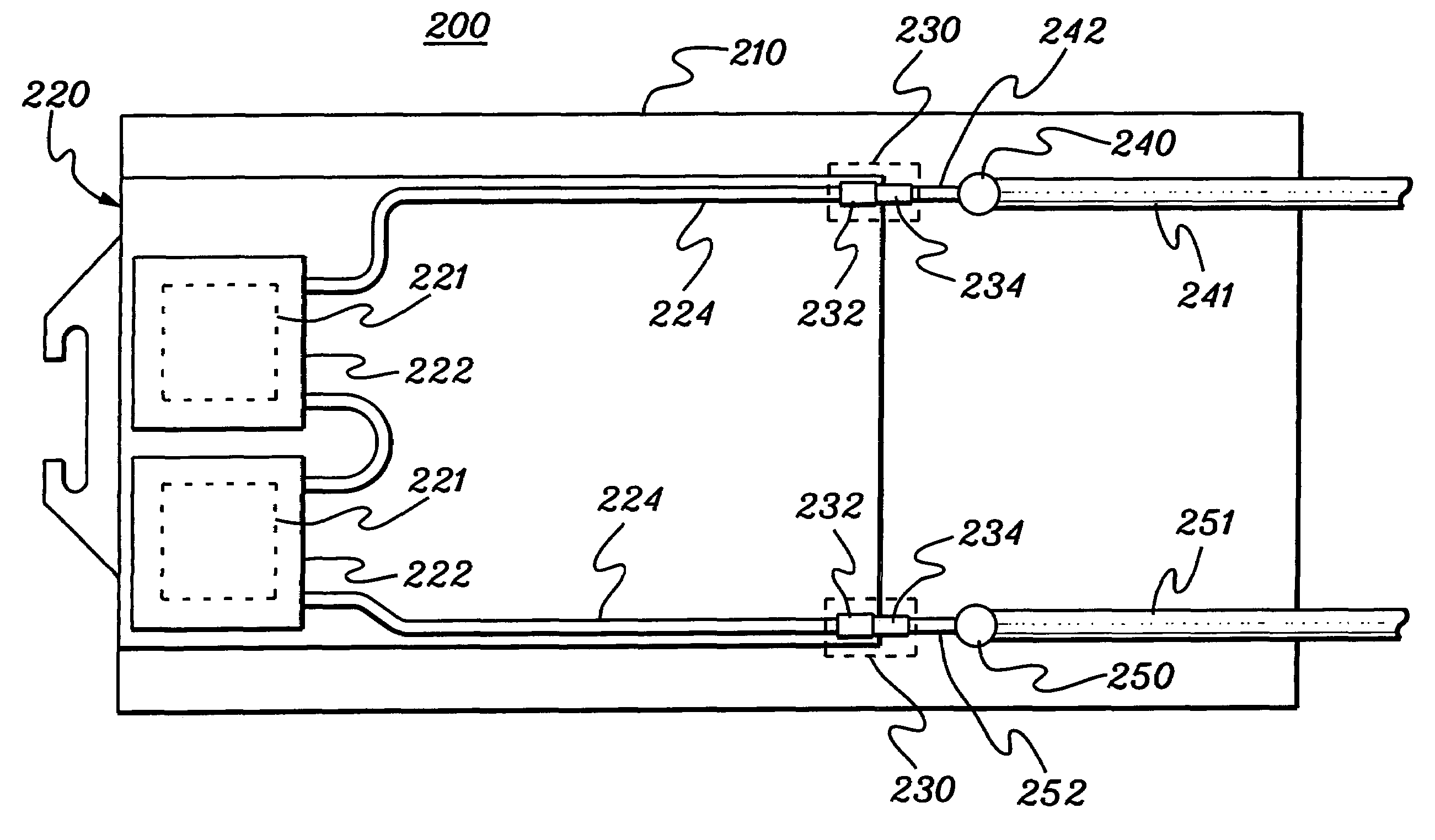
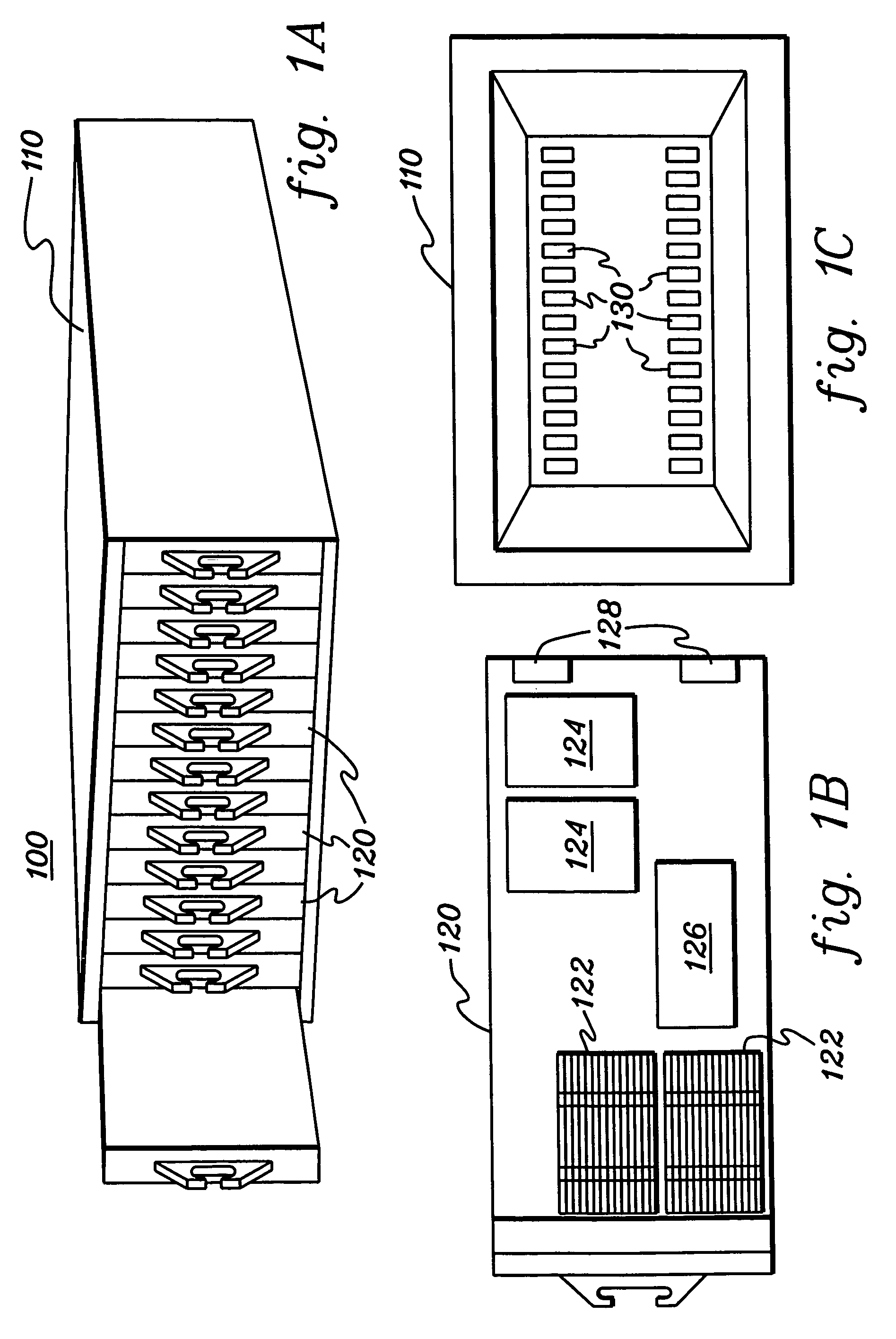
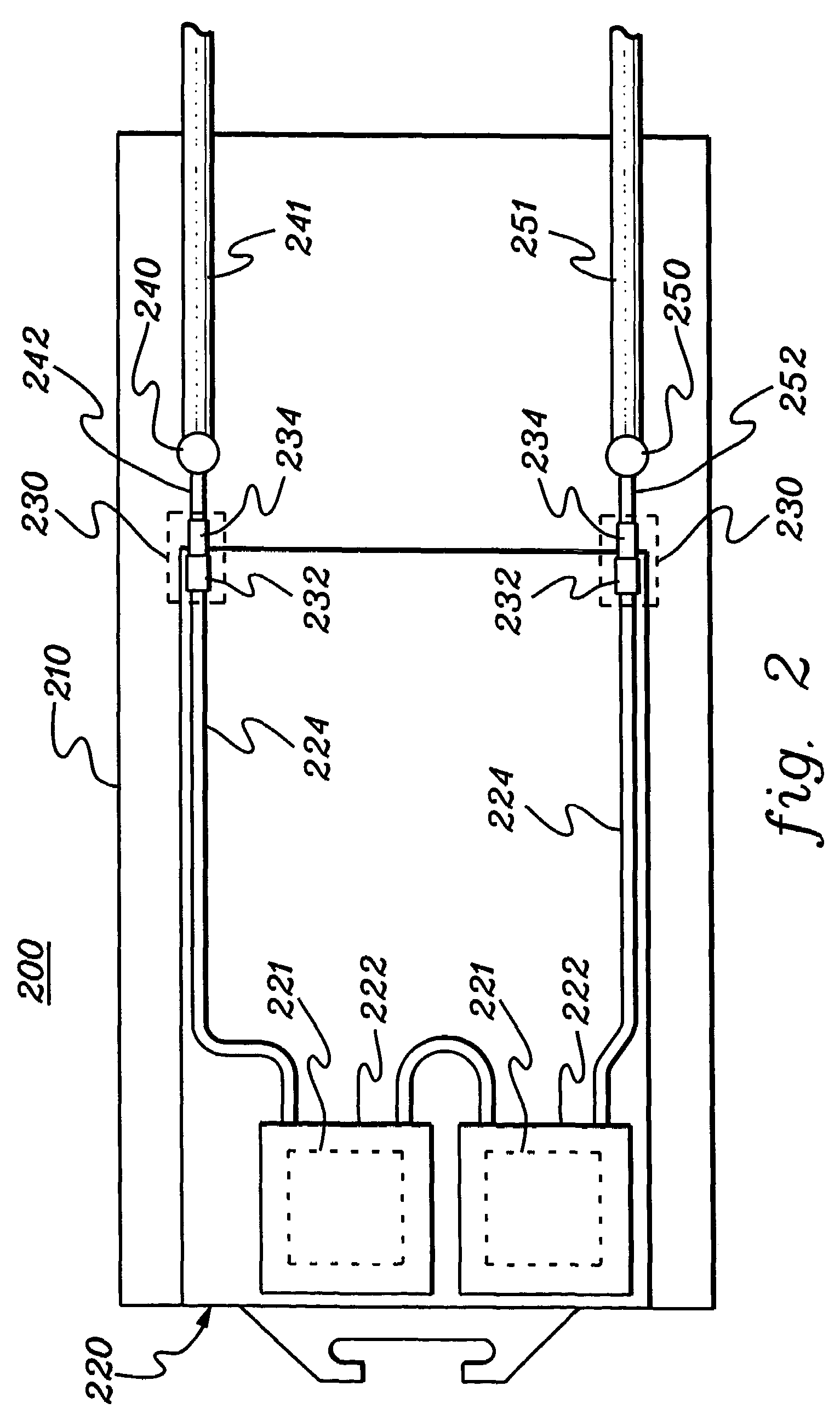
[0025]As used herein “liquid cooled electronics subsystem” refers to any receptacle, compartment, node, book, drawer, blade, etc., containing one or more heat generating components of a computer system or other electronics system employing liquid cooling. The term “electronics module” includes any heat generating component of a computer system or electronics system, and may be, for example, one or more integrated circuit devices, or one or more packaged electronics devices (such as a processor module). The term “electronics housing” includes any frame, rack, chassis, etc. designed to receive one or more liquid cooled electronics subsystems; and may be, for example, a stand alone computer processor having high, mid or low end processing capabilities. In one embodiment, an electronics housing may comprise one or more blade server system chassis, each having one or more blades requiring cooling.

[0026]By way of example, various aspects of the present invention are disclosed hereinbelow ...


PUM


Abstract

An isolation valve assembly, a coolant connect / disconnect assembly, a cooled multi-blade electronics center, and methods of fabrication thereof are provided employing an isolation valve and actuation mechanism. The isolation valve is disposed within at least one of a coolant supply or return line providing liquid coolant to the electronics subsystem. The actuation member is coupled to the isolation valve to automatically translate a linear motion, resulting from insertion of the electronics subsystem into the operational position within the electronics housing, into a rotational motion to open the isolation valve and allow coolant to pass. The actuation mechanism, which operates to automatically close the isolation valve when the liquid cooled electronics subsystem is withdrawn from the operational position, can be employed in combination with a compression valve coupling, with one fitting of the compression valve coupling being disposed serially in fluid communication with the isolation valve.

Description

TECHNICAL FIELD[0001]The present invention is directed to cooling assemblies and methods for removing heat from electronic devices and modules. More particularly, this invention relates to an isolation valve assembly for use with a liquid cooled electronics subsystem and associated electronics housing which supplies coolant to the liquid cooled electronics subsystem. Still more particularly, this invention relates to an enhanced connect / disconnect assembly for a thermal dissipation assembly extracting heat from heat generating components of an electronics subsystem disposed operationally within an electronics housing.BACKGROUND OF THE INVENTION[0002]As it is well known, as the circuit density of electronic chip devices increases in order to achieve faster and faster processing speeds, there is a correspondingly increasing demand for the removal of heat generated by these devices. The increased heat demand arises both because the circuit devices are packed more closely together and b...

Claims


Application Information

Patent Timeline
Patent Type & Authority Patents(United States)
IPC IPC(8): F25D23/12F16K31/44F28D15/00H05K7/20
CPCH05K7/20772
Inventor CAMPBELL, LEVI A.CHU, RICHARD C.ELLSWORTH, MICHAEL J.IYENGAR, MADHUSUDAN K.PORTER, DONALD W.SCHMIDT, ROGER R.SIMONS, ROBERT E.
Owner INT BUSINESS MASCH CORP
Why Eureka
Try Eureka