Method of manufacturing a press felt, and a press felt, with the shape of a closed loop

a technology of press felt and closed loop, which is applied in the direction of press section, knitting, weaving, etc., can solve the problems of limiting the length of the base fabric to be manufactured, affecting the quality of press felt, etc., so as to facilitate and speed up the manufacture of a planar component, firm and quick manufacturing, and easy to automate the effect of implementation

Active Publication Date: 2008-06-03
TAMFELT PMC OY
View PDF11 Cites 19 Cited by
  • Summary
  • Abstract
  • Description
  • Claims
  • Application Information

AI Technical Summary

Benefits of technology

[0010]An advantage of the invention is that it facilitates and speeds up the manufacture of a planar component since the component needs not be provided with seam loops in the weaving machine. Since seam loops are not needed to connect the joining edges, the joining edges can be formed anywhere in the planar component. The seam loops, however, have to be formed already in connection with weaving. In addition, the joint according to the invention provides a good base to which batt fibre can be attached. The joint is also firm and quick to manufacture. It is relatively easy to automate the implementation of the joint.
[0011]A preferred embodiment of the invention is based on the idea that at least one joining edge area of the planar component is provided with a thinned portion, where the density of transverse yarns is smaller in a predetermined section starting from the end of the component than in the rest of the component. Thanks to the thinning, the thickness of the overlapping joint can be decreased so that it does not significantly differ from the rest of the component structure. The thinning also affects the permeability of the overlapping joint so that it does not significantly differ from the rest of the component structure.
[0012]A preferred embodiment of the invention is based on the idea that thinning is implemented by removing several transverse yarns from the joining edge area after the manufacture of the component.
[0013]A preferred embodiment of the invention is based on the idea that a smaller number of transverse yarns are arranged in the joining edge areas than in the rest of the component during the manufacture of the planar component.
[0014]A preferred embodiment of the invention is based on the idea that the overlapping joining edge areas are attached to each other by welding.
[0015]A preferred embodiment of the invention is based on the idea that at least the portion with overlapping joining edge areas is provided with an attachment area, where the joining edge areas have been attached to each other undetachably. In addition, the boundary surface between the attachment area and the rest of the first component is made non-linear. Since the boundary surface is not clearly distinguishable, markings can be prevented.

Problems solved by technology

In that case, however, the width of the weaving machine restricts the length of the base fabric to be manufactured.
The seam loops may, however, cause markings on the web to be dried.
In addition, adherence of batt fibre to the area provided with seam loops may also pose a problem.

Method used


Image

  • Method of manufacturing a press felt, and a press felt, with the shape of a closed loop
  • Method of manufacturing a press felt, and a press felt, with the shape of a closed loop
  • Method of manufacturing a press felt, and a press felt, with the shape of a closed loop

Examples


Embodiment Construction

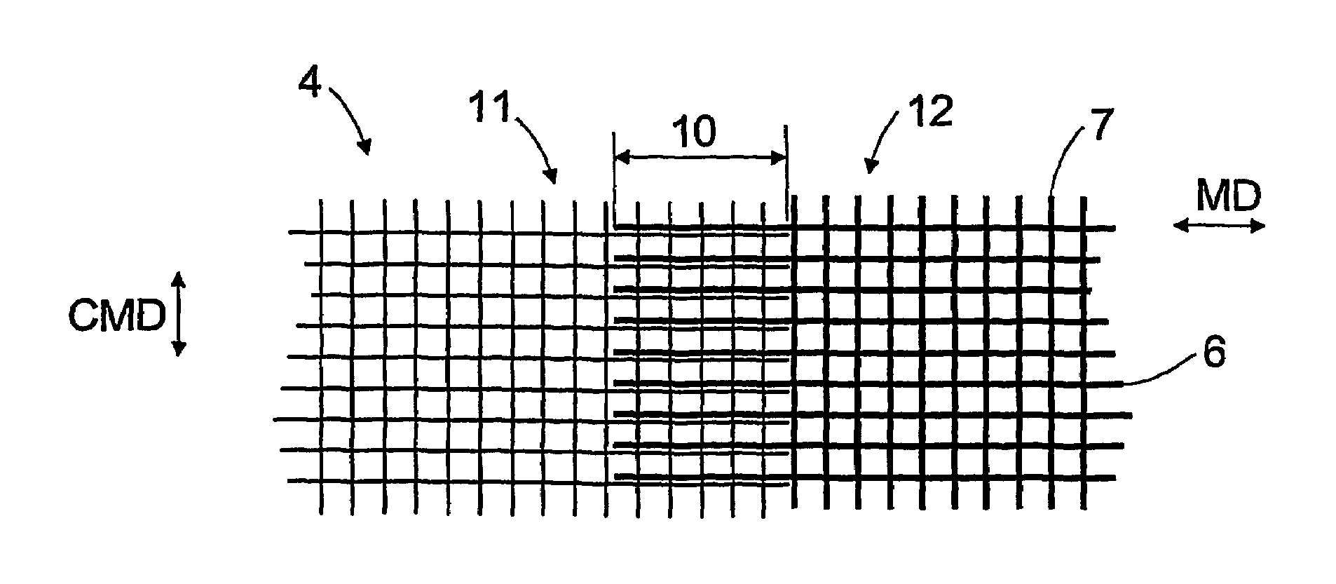
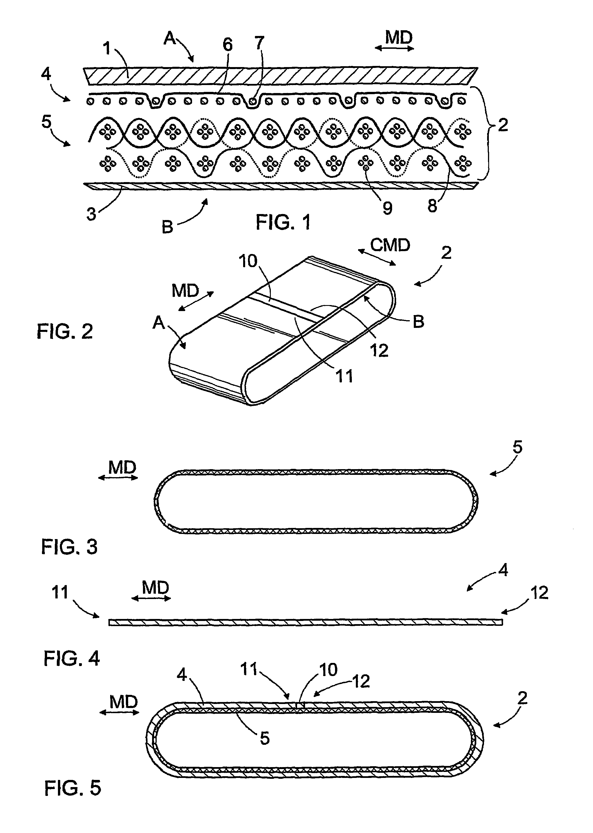
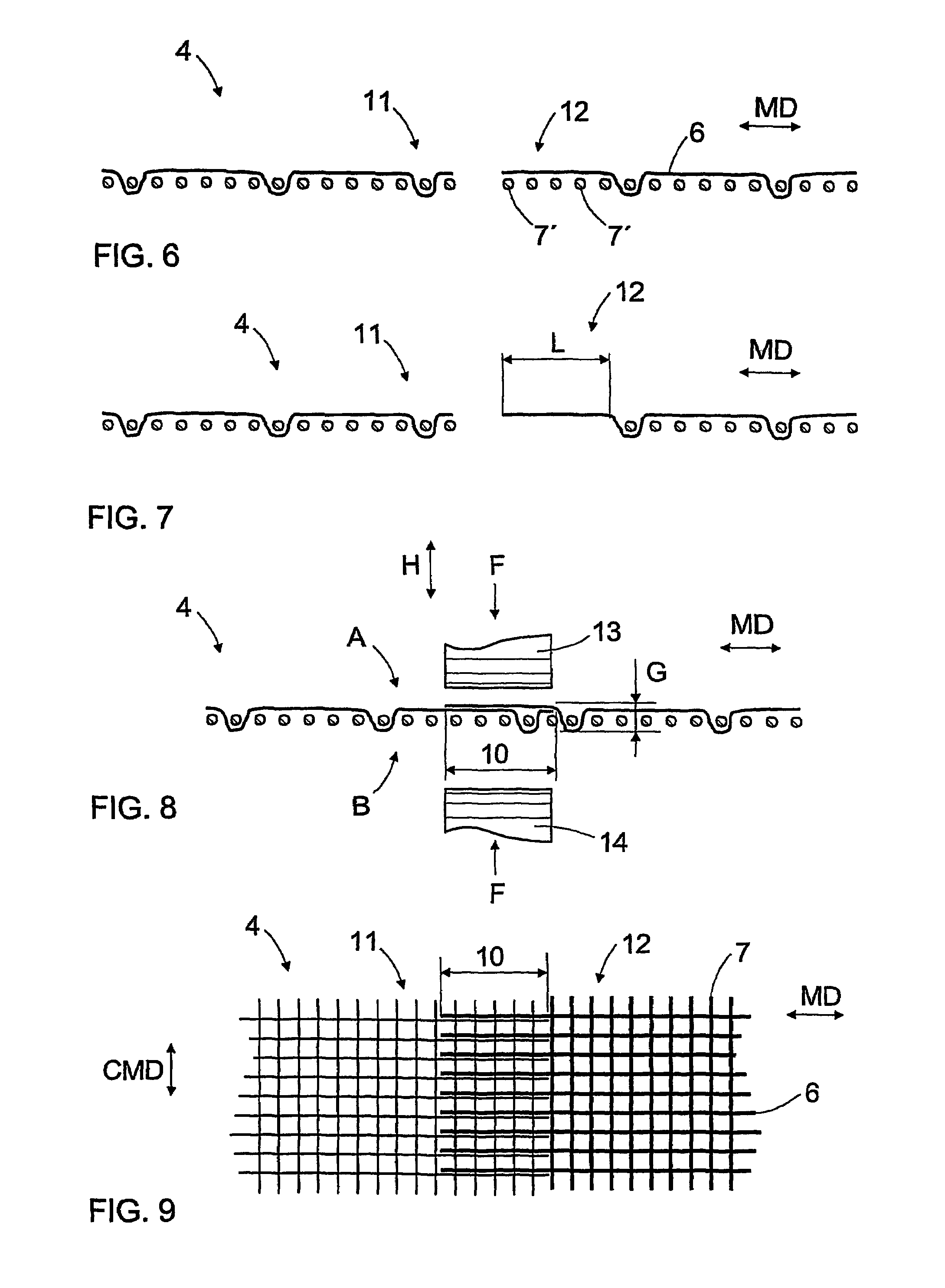
[0029]FIG. 1 illustrates a press felt according to the invention as a section in the paper machine direction MD. The felt illustrated in the figure comprises four layers attached to one another. On the felt surface A facing the web, there is a first batt fibre layer 1 as the outermost layer. Below the first batt fibre layer, there is a base fabric 2 consisting of two components, and further at the bottom of the felt, i.e. on the surface B facing the paper machine, there is a second batt fibre layer 3. The first batt fibre layer 1 prevents the generation of markings, i.e. a pattern caused by the weave of the base fabric, onto the web surface. In addition, water retention properties of the felt can also be affected by batt fibre. The first batt fibre layer 1 may consist of two or more thin layers, in which case there may be finer batt fibre on the surface of the batt fibre layer 1 and coarser batt fibre below it. The second batt fibre layer 3 at the bottom of the felt is not necessary...


PUM

PropertyMeasurementUnit
lengthaaaaaaaaaa
lengthaaaaaaaaaa
widthaaaaaaaaaa

Abstract

The invention relates to a method of manufacturing a press felt and to a press felt and a base fabric. The base fabric comprises at least a first planar compo-nent (4), which includes a first transverse (CMD) joining edge area (11) and a second transverse joining edge area (12). The joining edge areas (11, 12) are arranged to overlap each other and attached to each other undetachably.

Description

BACKGROUND OF THE INVENTION[0001]The invention relates to a method of manufacturing a press felt, the method comprising at least the following steps of: forming a base fabric whose at least one layer comprises at least a first planar component, which is formed from a plurality of longitudinal yarns that travel in the machine direction and transverse yarns that travel in the cross machine direction, and providing the first component with a first transverse joining edge area and a second transverse joining edge area; arranging the first and the second transverse joining edge area of the first component so that they overlap each other; and forming a base fabric with the shape of a closed loop; and attaching at least one batt fibre layer to the base fabric with the shape of a closed loop; and the method comprising attaching the joining edge areas to each other undetachably before the attachment of the batt fibre layer.[0002]The invention further relates to a press felt for a paper machi...

Claims


Application Information

Patent Timeline
Patent Type & Authority Patents(United States)
IPC IPC(8): D21F7/10B32B5/06D21F7/08
CPCD21F7/083D21F7/10Y10T428/192Y10S162/904Y10S162/90Y10T442/3724
Inventor SILAKOSKI, LEENA
Owner TAMFELT PMC OY
Why Eureka
Try Eureka