Filtration apparatus

a technology of filtration apparatus and filter body, which is applied in the direction of sedimentation settling tank, liquid displacement, separation process, etc., can solve the problems of high cost of filtration apparatus, low initial cost and low running cost, and achieve excellent water-shedding qualities

Inactive Publication Date: 2008-06-03
SANYO AQUA TECH +1
View PDF64 Cites 35 Cited by
  • Summary
  • Abstract
  • Description
  • Claims
  • Application Information

AI Technical Summary

Benefits of technology

[0039]Accordingly, the present invention enables a smooth formation of a second filter which is a self-generated film and a smooth filtration by means of the second filter by regulating the suction pressure of a pump.
[0052]The raw water tank 50 is formed of a material having excellent water-shedding qualities and thus, the gelatinous removables consolidate by a tensile force of a surface thereof and are moved into the recovery tank 15. The gelatinous removables can be prevented from adhering to inner walls of the raw water tank 50.

Problems solved by technology

At present, companies are faced with very important and challenging ecological issues such as reducing industrial waste, sorting out industrial waste and recycling or avoiding discharge of industrial waste into the nature.
Such wastewater is filtered using very expensive filtration apparatuses to remove the contaminants therein.
However, the usage of these filtration apparatuses is extremely difficult and becomes an environmental issue in itself due to a high running cost and equipment cost, etc. of the filtration process, etc.
As can be understood from the above, technology and techniques for wastewater treatment raise an important issue in terms of environmental pollution and recycling and therefore a system with a low initial cost and low running cost is promptly required.
Nevertheless, it is extremely difficult to specify the amount of chemicals that fully react and a large amount of chemicals which do not react is left.
In particular, if the amount of the chemicals is large, chemicals are left in the clear supernatant liquid and therefore, because chemicals remain in the filtered liquid, reuse thereof is impossible at when further chemical reactions need to be carried out.
It is therefore possible that they are discharged to the exterior and recovery thereof is very difficult.
Due to size considerations, initial cost of this system is expensive, reuse of water is difficult and the running cost generated by the use of chemicals is very expensive.
To summarize, running cost, including extremely high power consumption by the motor, high costs associated with replacement of the pump P and filter F, becomes extremely high.
Moreover, with the CMP method, in the dicing process, a very large amount of wastewater is discharged.
Consequently, when the slurry comprising very fine abrasive coating is filtered through the filter, particles enter the holes provided in the filter causing clogging.
The filter clogs very frequently so that it is impossible to filter a large amount of wastewater.
As can be understood from the above description, in order to remove as much as possible all materials that may cause damage to the environment and to recycle filtered fluid and removables separated in the filtration process, the wastewater filtration system becomes a huge system due to various additional apparatuses, thus triggering extremely high initial cost and running cost.
Accordingly, wastewater treatment apparatuses until now, could not be easily installed and used for wastewater treatment.
When using a self-generated film (pre-coat filter) to filter the wastewater, control of the pump carrying out filtration is very difficult.
This led to a reduction of filtration efficiency.
Also, when filtration is carried out in a filtration apparatus having a self-generated filter, there is no appropriate method of removing the self-generated film which clogged.

Method used


Image

  • Filtration apparatus
  • Filtration apparatus
  • Filtration apparatus

Examples


first embodiment

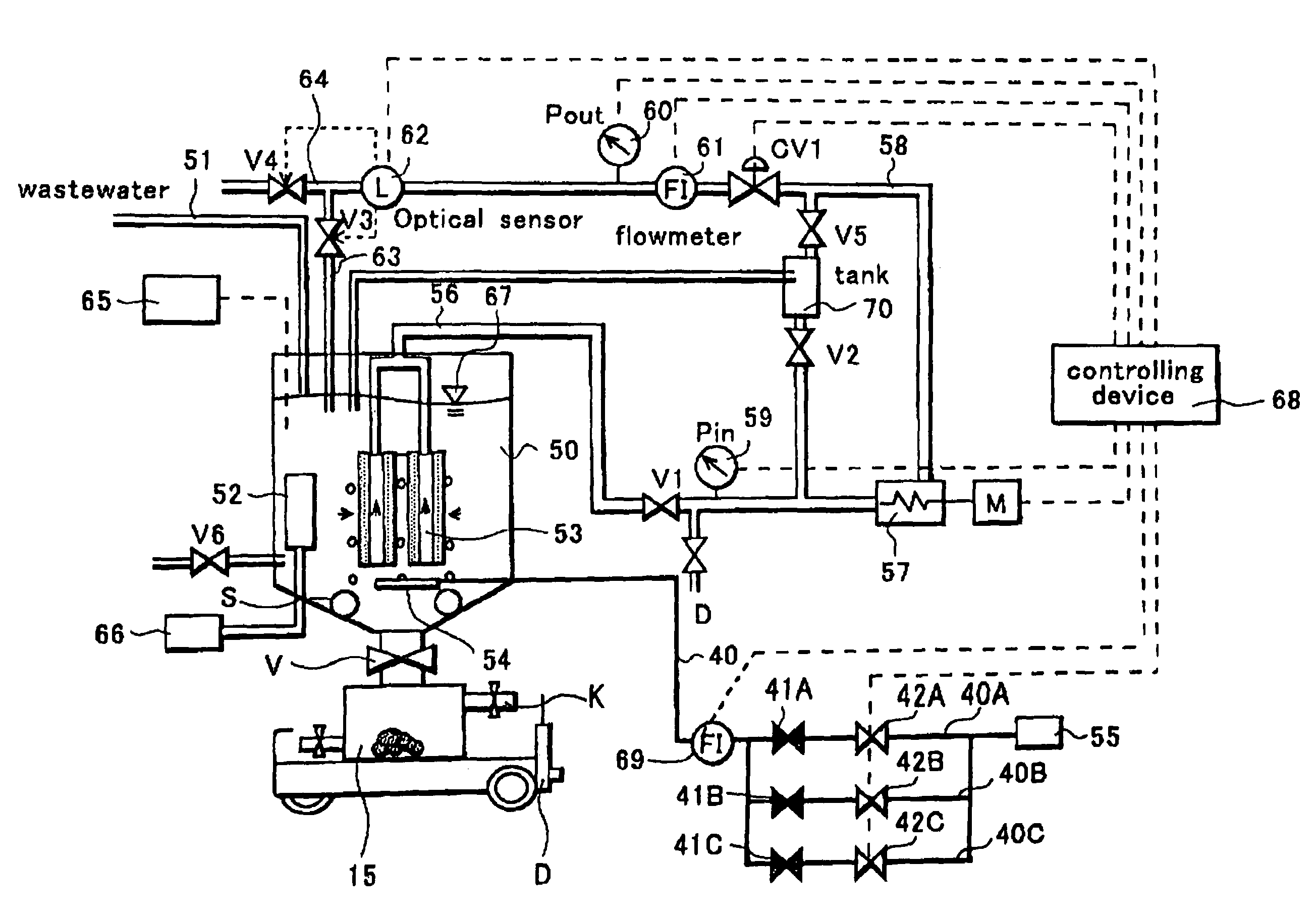
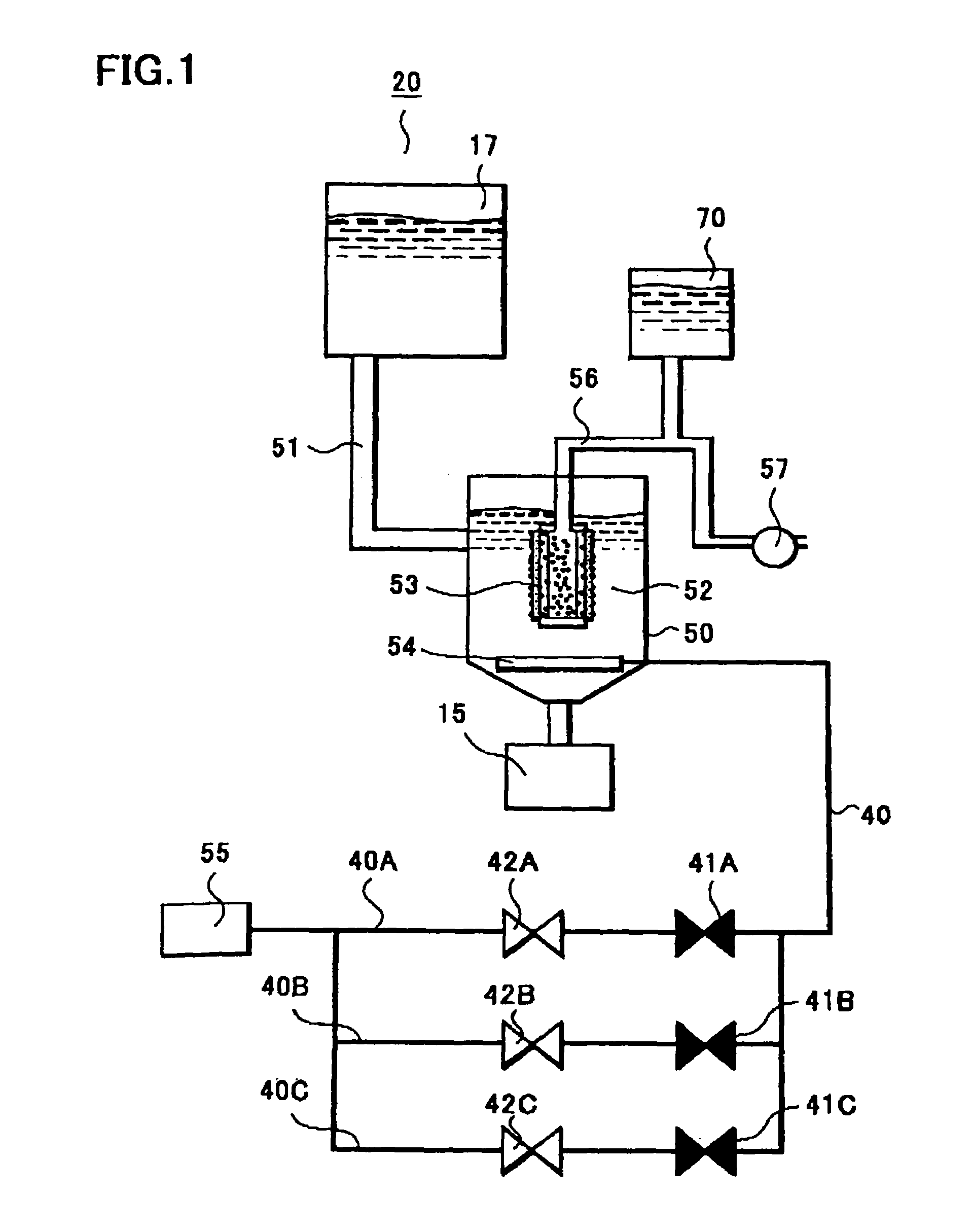
[0073]Configuration, etc. of a filtration apparatus 20 according to a first embodiment of the invention is described referring to FIG. 1. The filtration apparatus 20 comprises a tank 50 for housing a fluid comprising removables, a filter apparatus 53 for filtering the fluid, an air diffuser 54 as an air diffusion means, located at a lower part of the filter apparatus 53 and generating bubbles inside the fluid, an air pump 55 connected to the air diffuser 54 via an air pipe 40 and supplying gas, wherein the air pipe 40 is provided with an adjustment valve 41 regulated in advance so that a predetermined amount of gas is caused to pass, and a stop valve 42 for blocking or releasing the gas that passes inside the air pipe 40. A more detailed description of the configuration of the filtration apparatus 20 is next provided.

[0074]A raw water tank 50 as shown in FIG. 1 is provided in an upper part thereof with a pipe 51 as means for supplying wastewater. The pipe 51 supplies the fluid conta...

second embodiment

[0082]Configuration of a filtration apparatus according to a second embodiment of the invention is basically the same as that described in the first embodiment, consequently, description is given only of the differences therebetween.

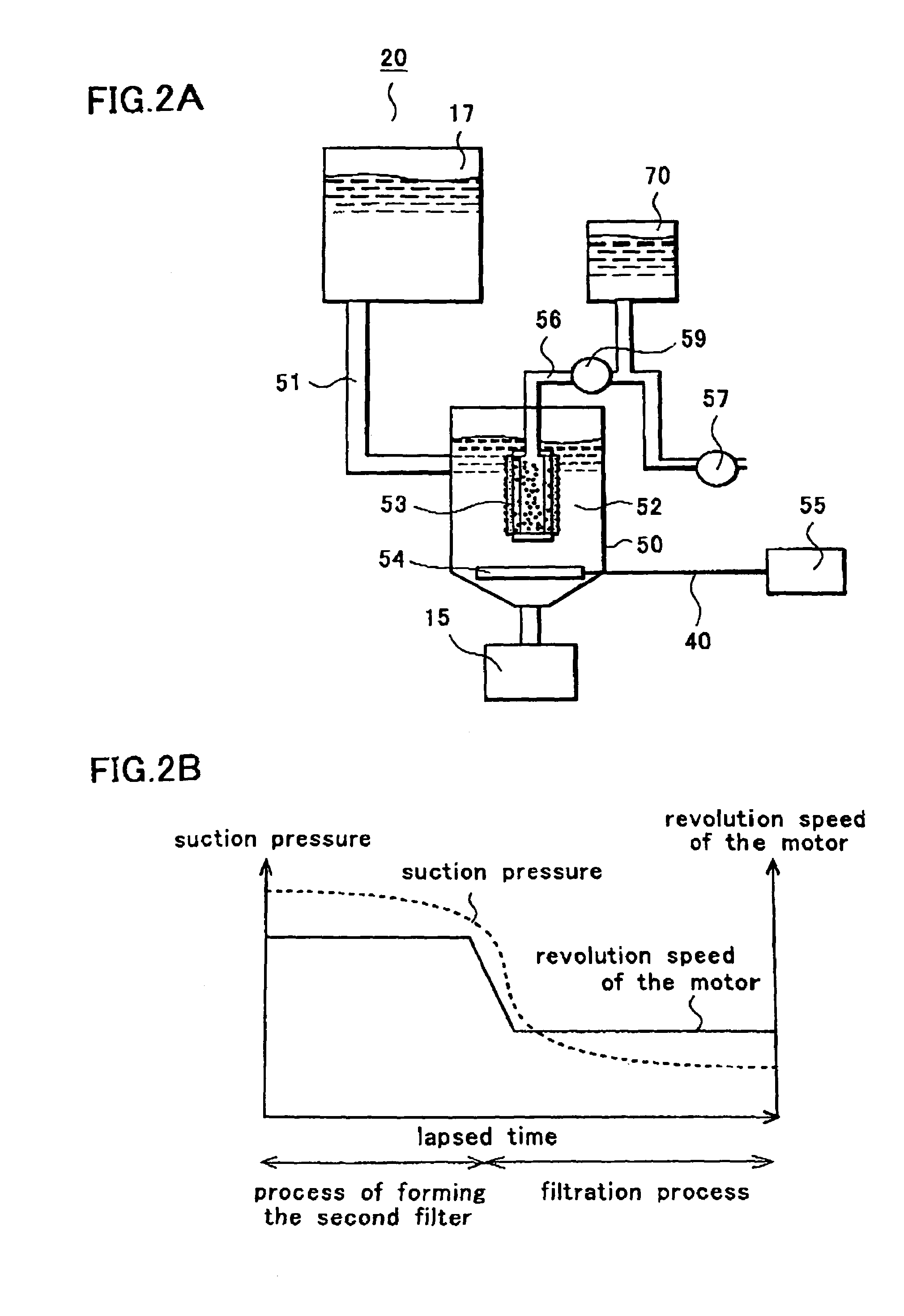
[0083]FIG. 2A is a schematic diagram of a filtration apparatus 20 according to a second embodiment of the present invention and FIG. 2B is a characteristics diagram showing variation in time of revolution speed of the motor and the suction pressure inside a pipe 56.

[0084]The filtration apparatus 20 shown in FIG. 2A comprises a raw water tank 50 for housing a fluid containing removables, a filter apparatus 53 comprising a first filter immersed inside the raw water tank 50 and a second filter comprising removables deposited on a surface of the first filter, a pump 57 connected to the filter apparatus 53 via a pipe 56, wherein the second filter is formed by the passage of the fluid through the first filter by applying a suction pressure from the pump 57 and...

third embodiment

[0094]Configuration of a filtration apparatus according to a third embodiment of the invention is basically the same as that described in the first embodiment, consequently, description is given only of the differences therebetween.

[0095]The configuration, etc. of a filtration apparatus 20 according to a third embodiment of the invention is described with reference to FIG. 3, where FIG. 3A is a schematic diagram of a filtration apparatus 20 and FIG. 3B is a cross-sectional enlarged view of a tapered lower part of a raw water tank 50.

[0096]The filtration apparatus 20 comprises a raw water tank 50 housing a fluid containing removables, a filter apparatus 53 immersed inside the raw water tank 50, a recovery tank 15 that communicates with a lower part of the raw water tank 50 via a valve V and where removables precipitate, wherein the recovery tank 15 is detachable from the raw water tank 50 and the removables precipitated in the recovery tank 15 are recovered by closing the valve V and...


PUM

PropertyMeasurementUnit
diameteraaaaaaaaaa
diameteraaaaaaaaaa
diameteraaaaaaaaaa

Abstract

A filtration apparatus is provided which is easy to maintain, manage and which enables preservation of filtration characteristics due to the fact that filtration is carried out by use of a gelatinous filter apparatus. In the filtration apparatus, filtration characteristics can be maintained by providing a bubble supplying mechanism for removing a sedimentary layer comprising removables that is formed on a surface of a filtration film and a filtration characteristics restoring mechanism for restoring the filter film clogged by the removables by causing a back-flow of filtered water accumulated in a cistern. Filtration apparatus maintenance and management are facilitated by improving recovery efficiency of the precipitated removables by tapering a lower part inside a raw water tank and providing a recovery tank for recovering removables via a valve.

Description

CROSS REFERENCE TO RELATED APPLICATIONS[0001]This application is a divisional of Ser. No. 10 / 831,585, filed Apr. 23, 2004.[0002]This application claims the benefit of priority to Japanese Patent Applications Nos. 2003-122583, 2003-122584, 2003-122585 and 2003-122586 filed on Apr. 25, 2003, contents thereof being hereby incorporated by reference.FIELD OF THE INVENTION[0003]The present invention relates to a filtration apparatus, and more particularly to a filtration apparatus which is easy to maintain and manage and which enables preservation of filtration characteristics.DESCRIPTION OF THE BACKGROUND ART[0004]At present, companies are faced with very important and challenging ecological issues such as reducing industrial waste, sorting out industrial waste and recycling or avoiding discharge of industrial waste into the nature. One type of industrial waste comprises various fluids containing contaminants.[0005]These fluids have different denominations, such as for instance sewage wa...

Claims


Application Information

Patent Timeline
Patent Type & Authority Patents(United States)
IPC IPC(8): B01D29/00B01D21/02B01D29/62B01D37/02B01D29/11
CPCB01D29/114B01D29/15B01D37/02B01D61/147B01D61/20B01D63/08B01D65/003B01D65/02B01D29/39B01D29/66B01D2321/04B01D2321/185B01D2315/06B01D63/089
Inventor UMEZAWA, HIROYUKIISEKI, MASAHIROTSUIHIJI, MOTOYUKI
Owner SANYO AQUA TECH
Why Eureka
Try Eureka