Voltage controlled oscillator with body of transistors bias control

a transistor and bias control technology, applied in the direction of oscillator generators, pulse automatic control, pulse technique, etc., can solve the problems of voltage control oscillator, consuming power considerably, low power,

Active Publication Date: 2008-06-03
SAMSUNG ELECTRO MECHANICS CO LTD
View PDF4 Cites 7 Cited by
  • Summary
  • Abstract
  • Description
  • Claims
  • Application Information

AI Technical Summary

Problems solved by technology

A telecommunication system applied to such applications characteristically needs to run on one long-lasting battery, and thus at low power.
Meanwhile a frequency synthesizer of an RF transceiver operates during both transmission and reception to generate a local oscillation frequency, thereby consuming power considerably.
But the conventional voltage controlled oscillator, when used at a low supply voltage of about 0.5V, cannot adopt a stack structure with many transistors.
Also, in this structure, many capacitor arrays are used to accommodate a desired frequency band, thereby creating parasitic components significantly.

Method used


Image

  • Voltage controlled oscillator with body of transistors bias control
  • Voltage controlled oscillator with body of transistors bias control
  • Voltage controlled oscillator with body of transistors bias control

Examples


first embodiment

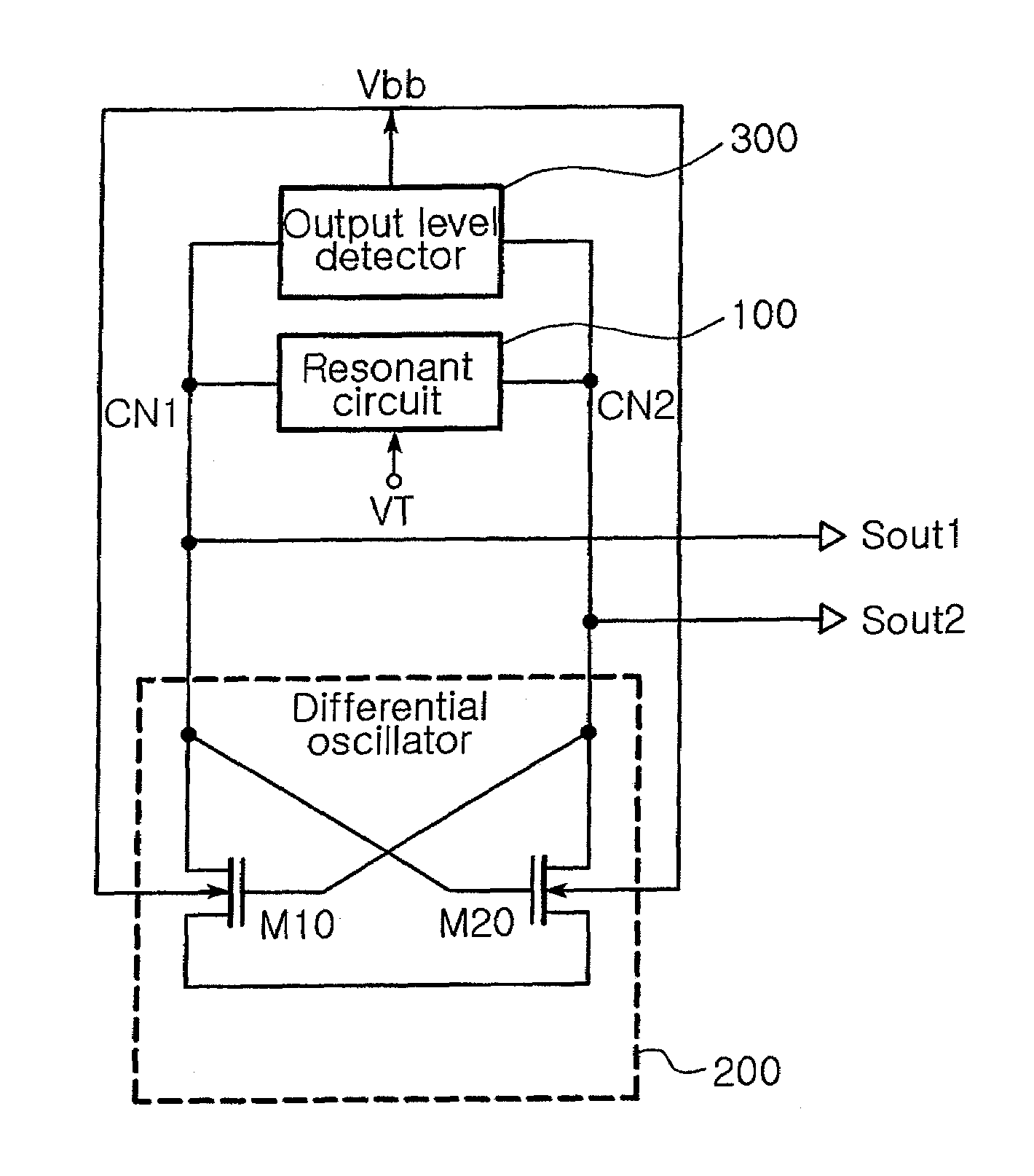
[0042]FIG. 3 is a circuit diagram illustrating a voltage controlled oscillator according to the invention.

[0043]Referring to FIG. 3, in the voltage controlled oscillator according to the first embodiment of the invention, each of first and second transistors M10 and M20 is configured as an n-channel Metal Oxide Semiconductor (MOS) transistor.

[0044]The first transistor M10 has a drain connected to a first connecting node CN1 between a first end of a resonant circuit 100 and a gate of the second transistor M20, a gate connected to a second connecting node CN2 between a second end of the resonant circuit 100 and a drain of the second transistor M20, a source connected to a ground, and a body connected to a body bias voltage Vbb of an output level detector 300.

[0045]The second transistor M20 has a drain connected to the second connecting node CN2 between the second end of the resonant circuit 100 and the gate of the first transistor M10, a gate connected to the first connecting node CN1...

second embodiment

[0049]FIG. 5 is a circuit diagram illustrating a voltage controlled oscillator according to the invention.

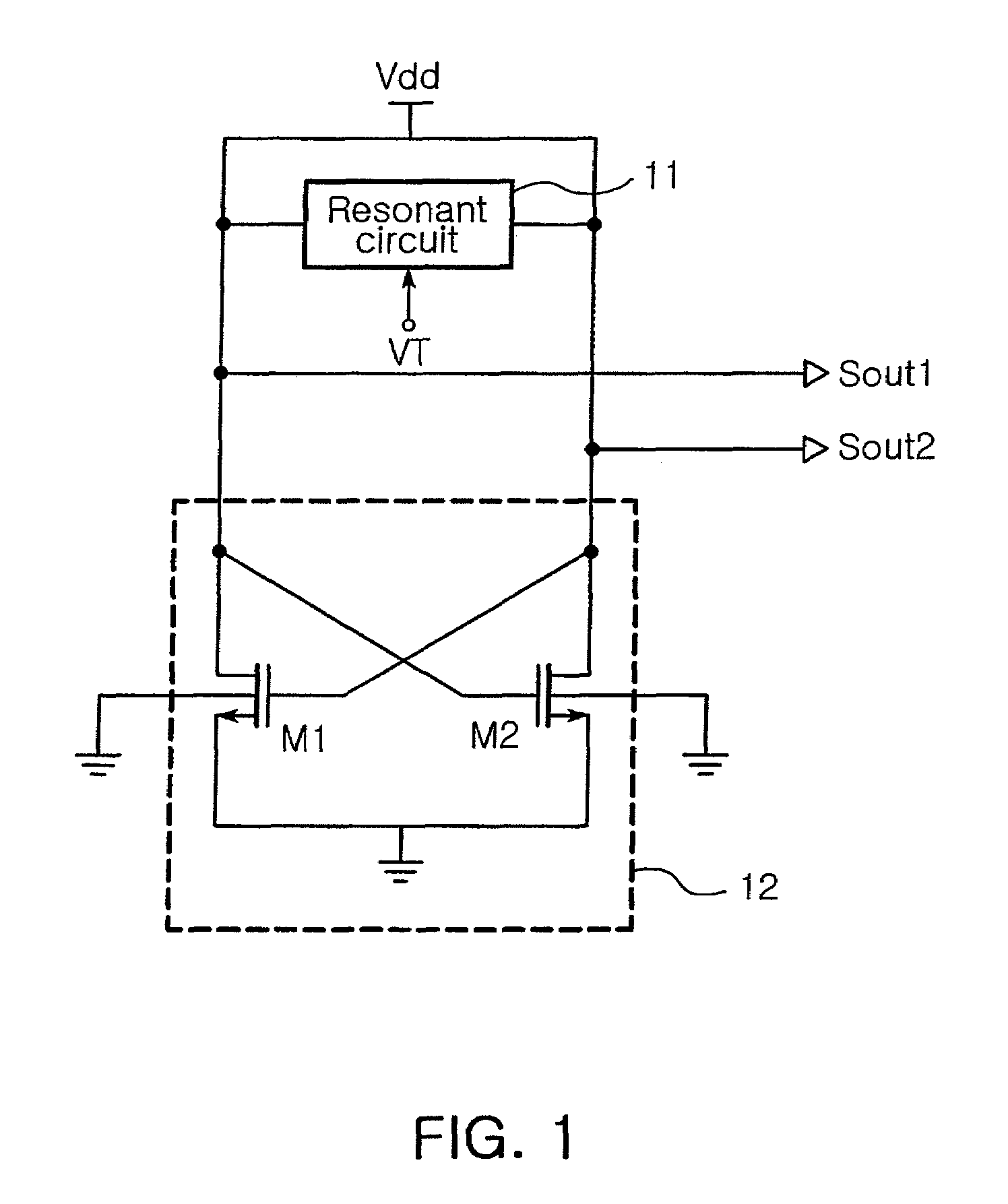
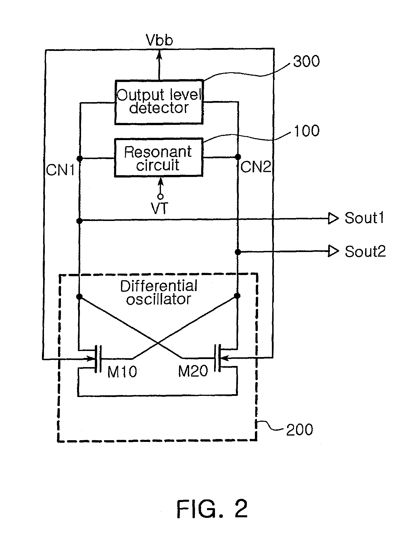
[0050]Referring to FIG. 5, in the voltage controlled oscillator according to the second embodiment of the invention, each of first and second transistors M10 and M20 is configured as a p-channel MOS transistor.

[0051]The first transistor M10 has a drain connected to a first connecting node CN1 between a first end of the resonant circuit 11 and a gate of the second transistor M20, a gate connected to a second connecting node CN2 between a second end of a resonant circuit 100 and a drain of the second transistor M20, a source connected to a supply voltage Vdd and a body connected to a body bias voltage of an output level detector 300.

[0052]The second transistor M20 has a drain connected to the second connecting node CN2 between a second end of the resonant circuit 100 and the gate of the first transistor M10, a gate connected to the first connecting node CN1 between the first end o...


PUM


Abstract

In a voltage controlled oscillator, a resonant circuit generates a resonant frequency in response to a tuning voltage. A differential oscillator includes first and second transistors differentially cross-coupled to the resonant circuit. The first and second transistors supply energy to the resonant circuit to oscillate the resonant frequency from the resonant circuit, thereby generating first and second oscillation signals having a phase difference of 180 degree. Also, the first and second transistors adjust the first and second oscillation signals to a uniform level in response to a body bias voltage. In addition, an output level detector detects a level of the first and second oscillation signals from the differential oscillator and supplies the body bias voltage corresponding to the detected level to a body of each of the first and second transistors.

Description

CLAIM OF PRIORITY[0001]This application claims the benefit of Korean Patent Application No. 2005-95747 filed on Oct. 11, 2005 in the Korean Intellectual Property Office, the disclosure of which is incorporated herein by reference.BACKGROUND OF THE INVENTION[0002]1. Field of the Invention[0003]The present invention relates to a voltage controlled oscillator (VCO) employed in a frequency synthesizer of a low-power system. More particularly, the present invention relates to a voltage controlled oscillator with body bias control which can generate an oscillation signal of a uniform level without being affected by changes in a supply power.[0004]2. Description of the Related Art[0005]Recently the IEEE 802.15.4 (ZigBee) standard has garnered attention and found its application in home network, security and logistics where short-distance and low-speed transmission is required. A telecommunication system applied to such applications characteristically needs to run on one long-lasting batter...

Claims


Application Information

Patent Timeline
Patent Type & Authority Patents(United States)
IPC IPC(8): H03L5/00H03B5/18
CPCH03L5/00H03B5/1228H03B5/1212H03B5/1243H03B5/1278H03B5/08H03B5/02
Inventor PARK, DONG MINCHO, SEONG HWANPARK, TAH JOONKWON, YONG ILLIM, JOON HYUNGKIM, MYEUNG SU
Owner SAMSUNG ELECTRO MECHANICS CO LTD
Why Eureka
Try Eureka