Two-channel imaging spectrometer utilizing shared objective, collimating, and imaging optics

a technology of imaging spectrometer and shared objective, which is applied in the direction of optical radiation measurement, instruments, spectrometry/spectrophotometry/monochromator, etc., can solve the problems of limitations of existing designs on the wavelengths that may be analysed, and the design of imaging spectrometers that do not permit hyperspectral imaging in two different disjoints, so as to reduce the size, weight, and cost of the two-channel spectrometer

Active Publication Date: 2008-06-03
RAYTHEON CO
View PDF9 Cites 48 Cited by
  • Summary
  • Abstract
  • Description
  • Claims
  • Application Information

AI Technical Summary

Benefits of technology

[0012]The present approach uses shared optical components where possible. The shared optical components are selected to be compatible with the two different wavelength ranges, and are therefore preferably all-reflective in construction. The non-shared optical components are respectively selected and optimized for the different wavelength ranges, while being compatible with the shared optical components. This design architecture minimizes the size, weight, and cost of the two-channel spectrometer, an important consideration for many applications.

Problems solved by technology

However, the existing designs have limitations on the wavelengths that may be analyzed.
The existing designs of imaging spectrometers do not permit hyperspectral imaging in two different disjoint, well-separated spectral bands such as those discussed.

Method used


Image

  • Two-channel imaging spectrometer utilizing shared objective, collimating, and imaging optics
  • Two-channel imaging spectrometer utilizing shared objective, collimating, and imaging optics
  • Two-channel imaging spectrometer utilizing shared objective, collimating, and imaging optics

Examples


Embodiment Construction

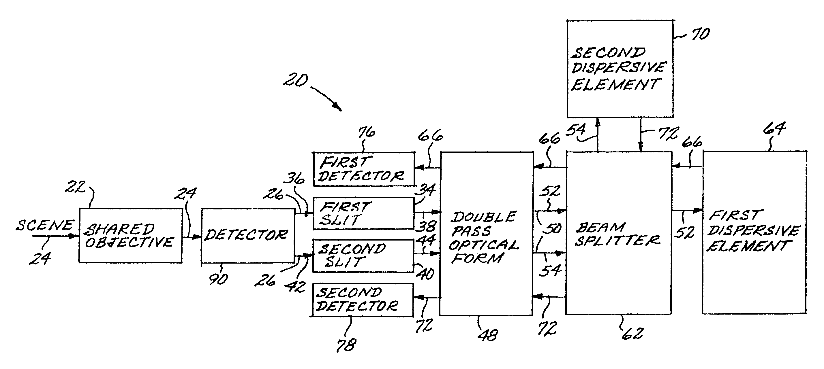
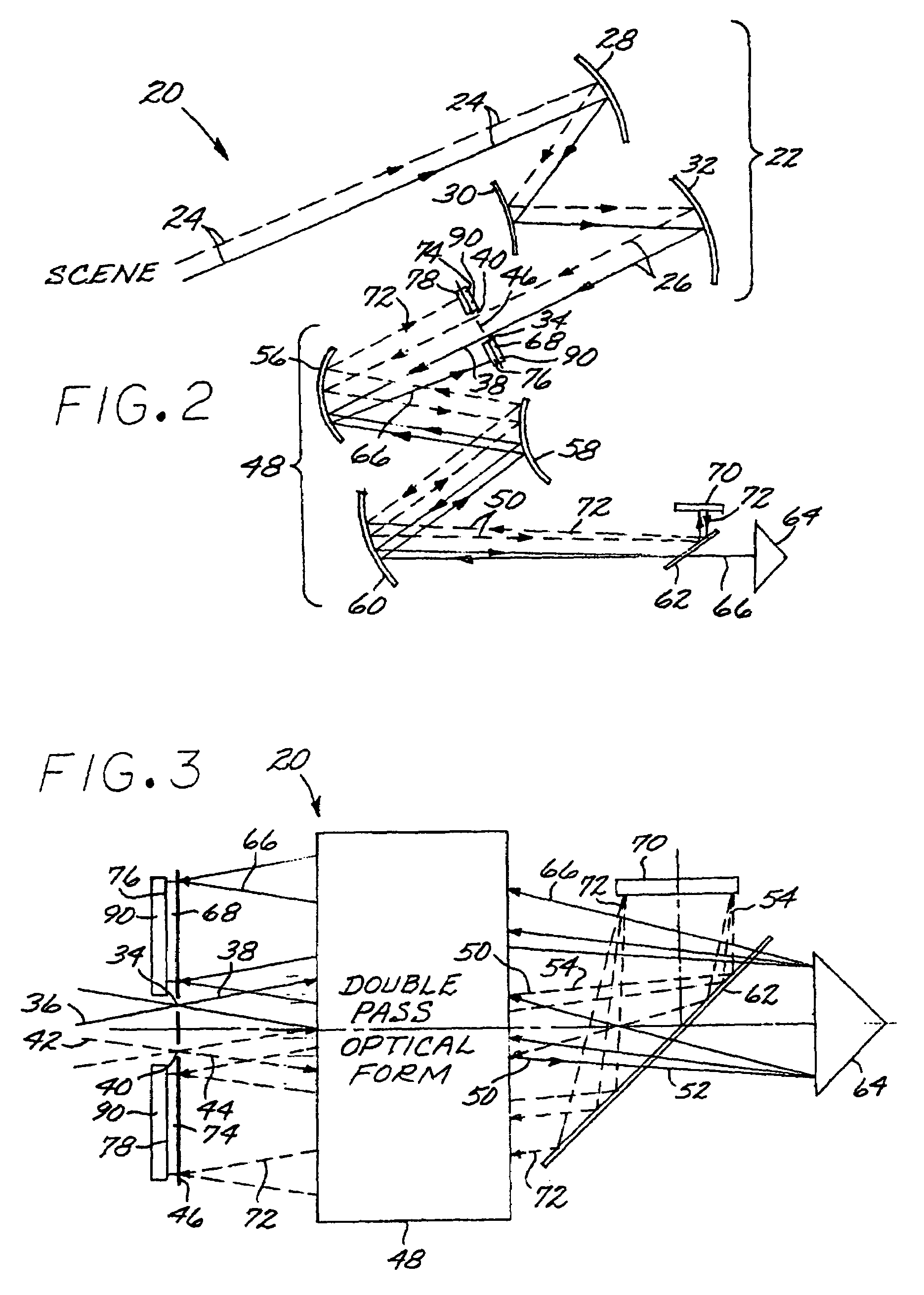
[0018]FIGS. 1-4 depict a preferred embodiment of a two-channel spectrometer 20. The two-channel spectrometer 20 includes a shared objective 22 having an input 24 from a scene being viewed, and an output beam 26. As used herein, “shared” means that the single element or optical module is utilized by both of the two channels or wavelength ranges. That is, there is a single objective 22 used by light of both wavelength ranges, and not a separate objective for each wavelength range. The shared objective 22 may be of any operable form, but it is strongly preferred that the shared objective 22 be an all-reflective objective, made solely of mirrors and with no lenses. The index of refraction of a lens is dependent upon the wavelength of the light being refracted, and the effect on performance in the present circumstances would be unacceptable in most cases. Thus, the objective 22 is preferably made only of mirrors.

[0019]FIG. 2 illustrates a preferred form of the shared all-reflective objec...


PUM


Abstract

A two-channel spectrometer has a shared objective and a pair of slits at a common image plane. Each of the slits receives a portion of the output beam of the shared objective and is optimized for transmitting different wavelengths. A shared double-pass reflective triplet receives the output beams of the slits. The output of the reflective triplet is incident upon a beamsplitter, which sends a collimated first reflective triplet output of a first wavelength to a first dispersive element, and a collimated second reflective triplet output of a second wavelength to a second dispersive element. The outputs of the dispersive elements are directed back to the beamsplitter and the reflective triplet to imaging detectors located at two different locations of the common image plane.

Description

[0001]This invention relates to an optical imaging spectrometer and, more particularly, to an optical spectrometer that provides hyperspectral imaging of a scene in two significantly different wavelength bands.BACKGROUND OF THE INVENTION[0002]Imaging spectrometers that form high-resolution images in a wide range of spectral bands are used in scientific, military, and resource-sensing applications. Such spectrometers provide an image and also a spectral analysis of the image in a selected wavelength band. However, the existing designs have limitations on the wavelengths that may be analyzed. In developing the present invention, the inventor has observed that in some applications it would be useful to simultaneously assess the image in two spectral bands that are disjoint and well separated. For example, the reflective / emissive spectral band of 0.5-5 micrometers wavelength yields visible and mid-infrared information, and the long wavelength infrared band of 7.5-12.5 micrometers yields...

Claims


Application Information

Patent Timeline
Patent Type & Authority Patents(United States)
IPC IPC(8): G01J3/28
CPCG01J3/02G01J3/0208G01J3/0256G01J3/0291G01J3/0294G01J3/04G01J3/2823G01J3/12
Inventor COOK, LACY G.
Owner RAYTHEON CO
Why Eureka
Try Eureka