Multipoint photonic doppler velocimetry using optical lens elements

a technology of optical lens elements and photonic doppler, which is applied in the field of photonic doppler velocimetry, can solve the problems of affecting the accuracy of measurement results, so as to increase the surface density coverage and increase the measurement point density

Inactive Publication Date: 2014-05-01
NAT SECURITY TECH
View PDF3 Cites 5 Cited by
  • Summary
  • Abstract
  • Description
  • Claims
  • Application Information

AI Technical Summary

Benefits of technology

[0008]An array of single-mode optical fibers sends laser light through the fisheye lens toward the surface. In one embodiment, the lens consists of an index-matching positive element, two positive doublet groups, and two negative singlet elements. The optical design minimizes beam diameters, physical size, and back reflections for excellent signal collection. The fiber array projected through the fisheye lens provides many measurement points of surface coverage over a hemisphere with very little crosstalk. The probe measures surface movement with only a small encroachment into the center of the cavity.
[0009]The fiber array is coupled to the index-matching element using index-matching gel. The array is bonded and sealed into a blast tube for ease of assembly and focusing. This configuration also allows the fiber array to be flat polished at a common object plane. In areas where increased measurement point density is desired, the fibers can be close packed. To further increase surface density coverage, smaller diameter cladding optical fibers may be used.

Problems solved by technology

Various solutions have been proposed to record the movement of the surface, but each of these various solutions suffer from various drawbacks.
However, longer pins can interfere with the surface movement and interfere with the shorter pins.
As a result, data may be corrupted by the interference.
In addition, data is only collected by a pin when that pin contacts the moving surface.
Moreover, a dense array of pins at many lengths is needed and this density may not be possible to achieve while also achieving desired data recordation.
This solution provided optic monitoring but it suffered from being size limited.
As the number of optic fiber points is increased, this probe eventually comes to its limit in how small the entire group can be made, while still having reasonable optical fiber bending radii.

Method used


Image

  • Multipoint photonic doppler velocimetry using optical lens elements
  • Multipoint photonic doppler velocimetry using optical lens elements
  • Multipoint photonic doppler velocimetry using optical lens elements

Examples


example embodiment

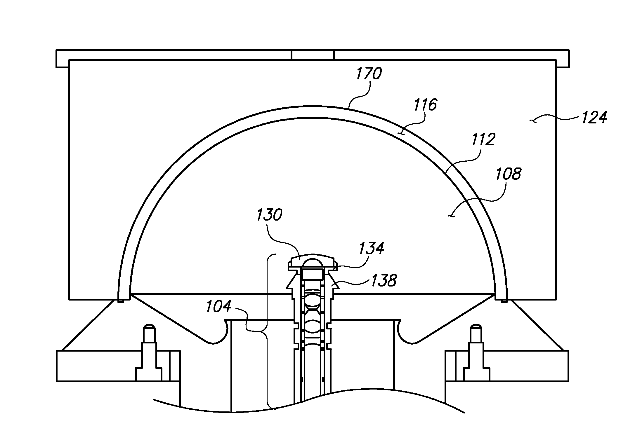
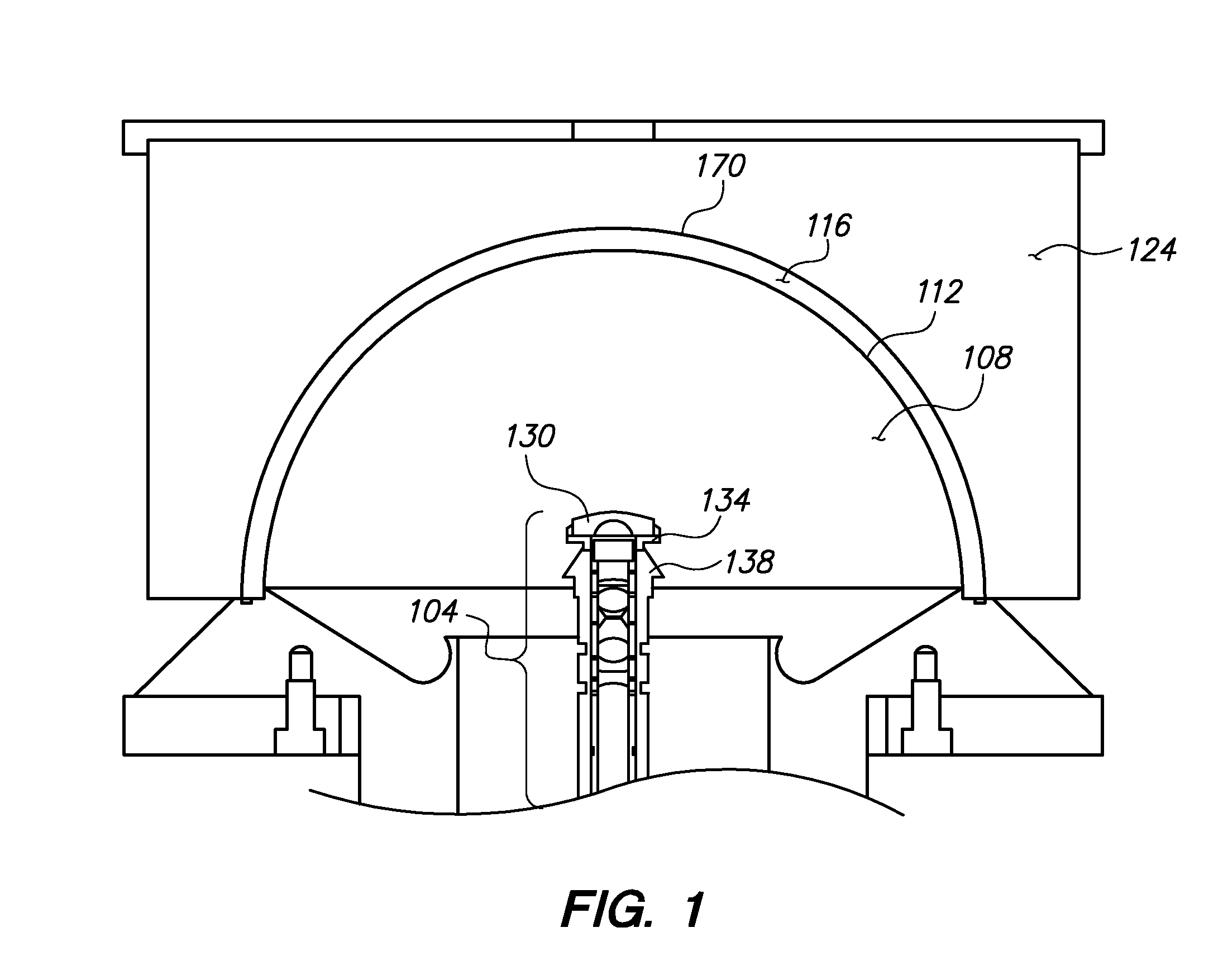
[0059]A series of live dynamic PDV tests within hemispherical shells were fielded using a discrete collimator multipoint ball probe, a multiple lens array probe, and a fisheye probe design (described in the next section). All three gave high-quality data during testing. The fisheye lens' performance stood out over prior art probes in several ways.

[0060]First, the fisheye element does not encroach into the center of the imploding hemisphere. This is important because experimentalists ideally want the measurement to record data until the shock wave impacts the probe. Therefore, the smaller the probe the better it will record late-time information. Second, the physical size of the waist near the center of the cavity is smaller. This helps to fit the probe through a small opening for blast mitigation. Third, angular coverage can be more complete. Fourth, the fisheye probe is easier to assemble than prior art multipoint probes.

[0061]During these tests to minimize costs, the PDV recording...


PUM


Abstract

A probe including a fisheye lens is disclosed to measure the velocity distribution of a moving surface along many lines of sight. Laser light, directed to the surface and then reflected back from the surface, is Doppler shifted by the moving surface, collected into fisheye lens, and then directed to detection equipment through optic fibers. The received light is mixed with reference laser light and using photonic Doppler velocimetry, a continuous time record of the surface movement is obtained. An array of single-mode optical fibers provides an optic signal to an index-matching lens and eventually to a fisheye lens. The fiber array flat polished and coupled to the index-matching lens using index-matching gel. Numerous fibers in a fiber array project numerous rays through the fisheye lens which in turn project many measurement points at numerous different locations to establish surface coverage over a hemispherical shape with very little crosstalk.

Description

STATEMENT REGARDING FEDERAL RIGHTS[0001]This invention was made with government support under Contract No. DE-AC52-06NA25946 and was awarded by the U.S. Department of Energy, National Nuclear Security Administration. The government has certain rights in the invention.FIELD OF THE INVENTION[0002]This invention relates to photonic Doppler velocimetry and in particular to a method and apparatus for multipoint photonic Doppler velocimetry using optical lens elements.RELATED ART[0003]Photonic Doppler velocimetry (PDV) can be used to monitor movement of a curved surface that is moving along multiple points, such as during an experiment. The movement of the curved surface may occur due to an implosion, explosion, or any other force or factor that causes movement of the surface. Such movement often occurs during dynamic material experiments. These dynamic material experiments frequently involve complicated geometries and therefore large numbers of data points are a distinct advantage. Vario...

Claims


Application Information

Patent Timeline
Patent Type & Authority Applications(United States)
IPC IPC(8): G02B6/32G01S17/58
CPCG02B6/32G01S17/58G01S7/4812G01S7/4818G02B13/06
Inventor FROGGET, BRENT COPELYROMERO, VINCENT TODD
Owner NAT SECURITY TECH
Why Eureka
Try Eureka