Cooling system for computer hardware

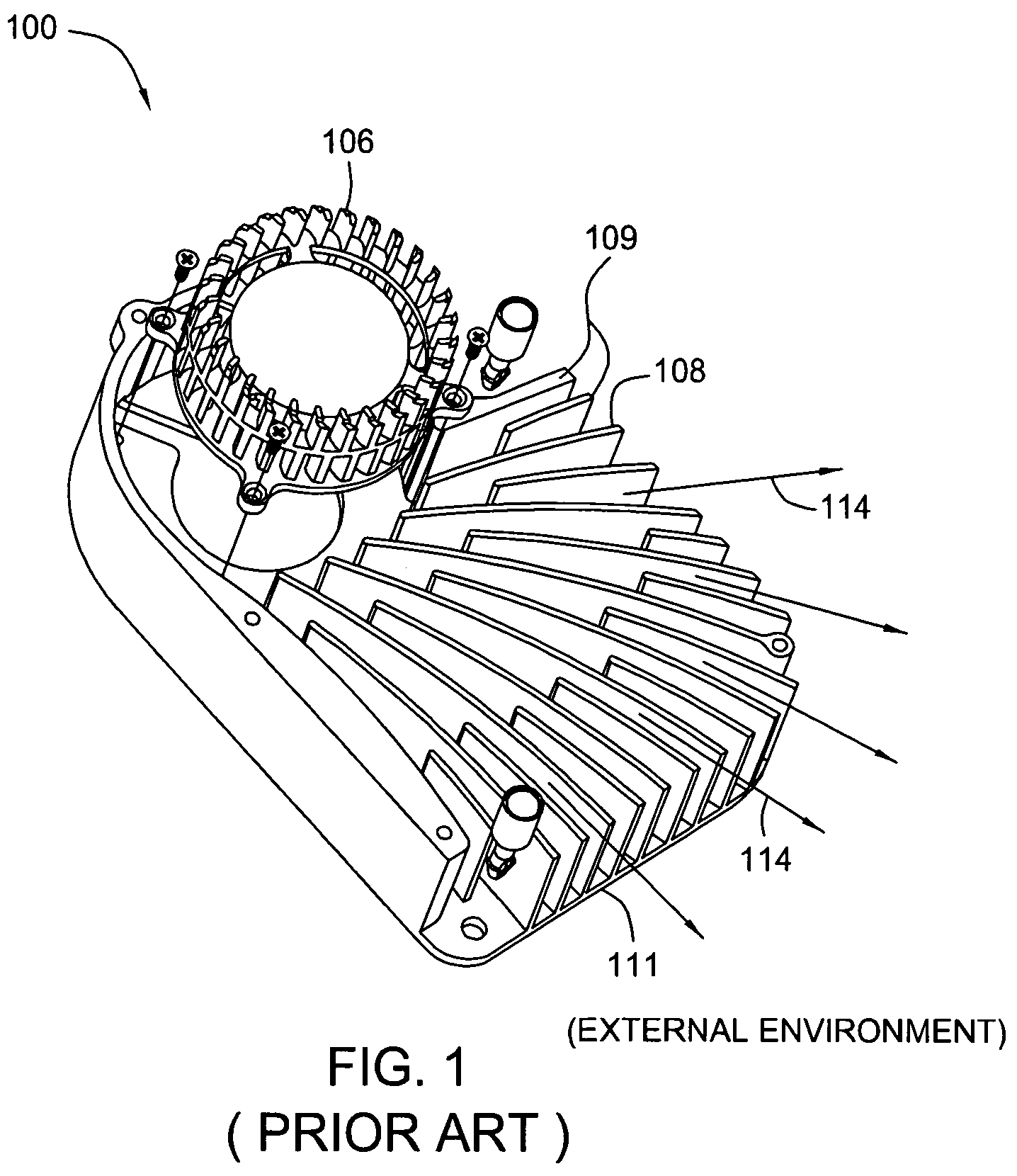
a cooling system and computer hardware technology, applied in the direction of electrical apparatus casings/cabinets/drawers, power cables, semiconductor/solid-state device details, etc., can solve the problems of poor heat transfer, gpu b>216/b> tending to generate a large amount of heat during operation, and reducing the overall efficiency of the cooling system b>100, so as to achieve more efficient cooling system and increase the effective area of surfaces

Active Publication Date: 2008-06-03
NVIDIA CORP
View PDF27 Cites 46 Cited by
  • Summary
  • Abstract
  • Description
  • Claims
  • Application Information

AI Technical Summary

Benefits of technology

[0014]One advantage of the disclosed cooling system is that it more equally distributes heat across the fins and more equally distributes airflow across surfaces of the fins. The design increases the effective area of surfaces of the fins used in transferring heat from the heat-generating electronic device to the air, resulting in a more efficient cooling system.

Problems solved by technology

Because the computational requirements of GPU 216 are typically quite substantial, GPU 216 tends to generate a large amount of heat during operation.
One drawback to using cooling system 100 is that the blower / fan 106 generates an unequal velocity profile through the fins 109 such that more air passes over the middle portion of each fin 109 as compared to the upper and lower portions of each fin 109.
This results in poor heat transfer from the upper and lower portions of each fin to the air leading to a lower overall efficiency of the cooling system 100.
Another drawback is that the size of the dedicated blower / fan within cooling system 100 is such that the blower / fan must be operated at a relatively high speed to generate the necessary airflow over the heat transfer surface area of cooling system 100.
High speed operation tends to produce a substantial amount of unwanted acoustic noise, which is annoying to users of computing device 200.
Yet another drawback is that conventional cooling systems employing blowers / fans are proving inadequate to meet the ever increasing heat dissipation requirements resulting from the rapid progression of graphics card capabilities.
Further compounding this issue is the fact that while graphics cards are becoming more powerful, the available space for cooling systems remains the same.

Method used


Image

  • Cooling system for computer hardware
  • Cooling system for computer hardware
  • Cooling system for computer hardware

Examples


Embodiment Construction

)

[0019]All references to directions in describing parts, such as top and bottom are for convenience and not meant to limit embodiments of the invention in any way.

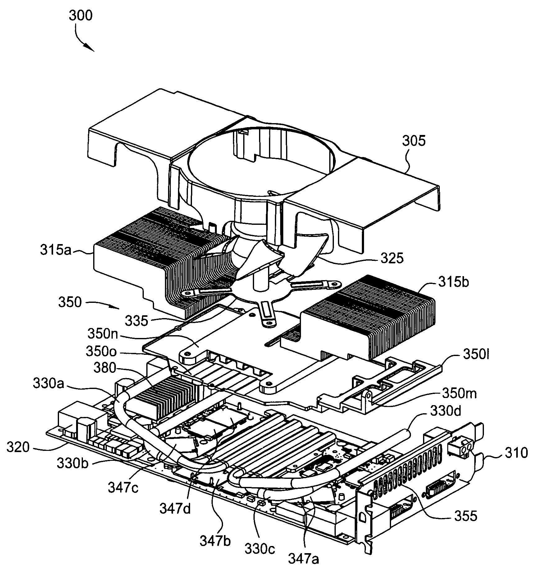
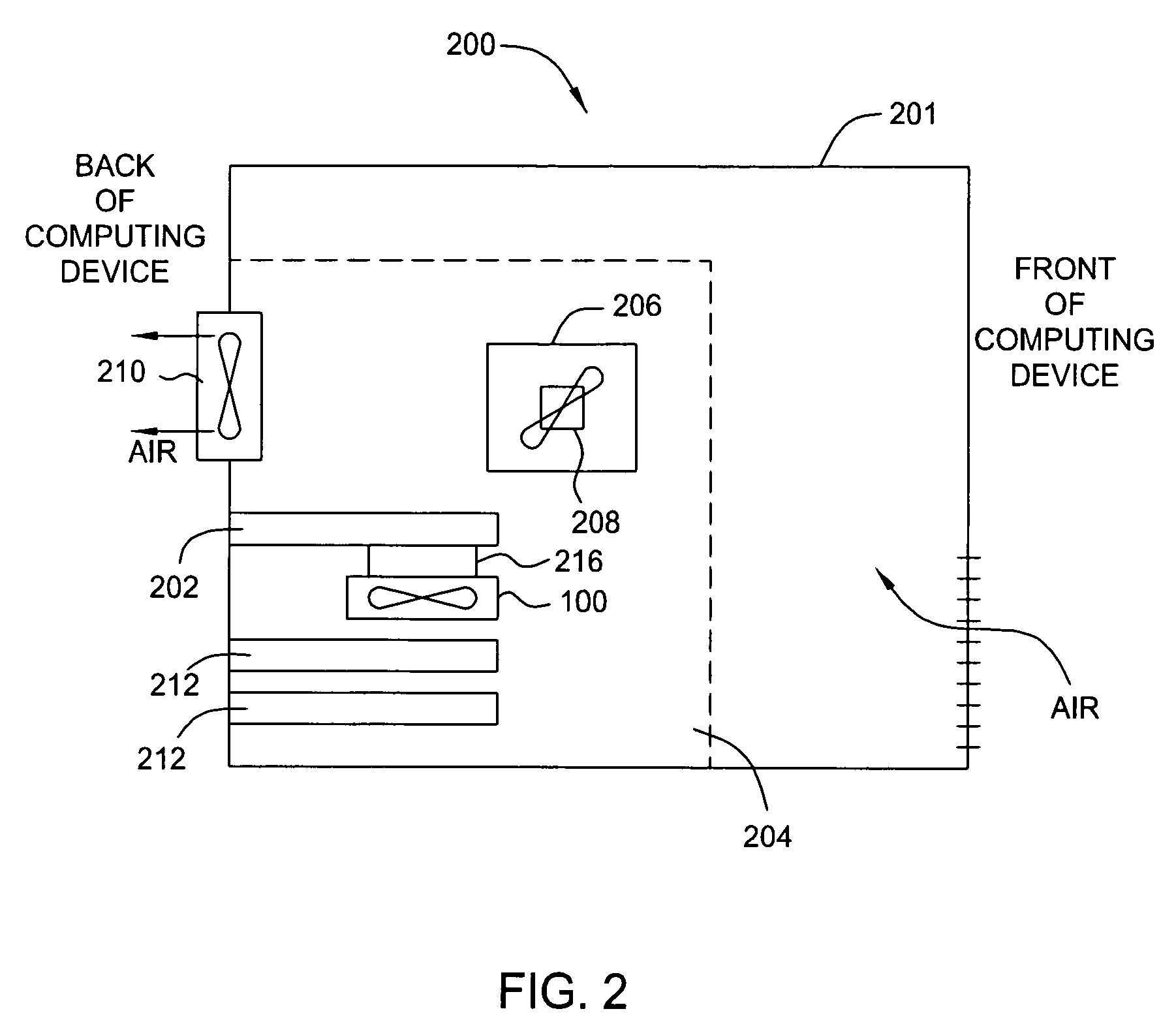
[0020]FIGS. 3A-J are various views of a cooling system 300, or components thereof, used to cool a heat-generating electronic device, according to one embodiment of the present invention. A shroud 305 of the cooling system has been omitted from FIGS. 3A and 3D-3F for the sake of illustration. Referring to FIG. 3B, as shown, cooling system 300 is configured to be thermally and structurally coupled to a printed circuit board (PCB), such as the graphics card 320 or graphics card 202 of FIG. 2. Mounted on a top side, the graphics card 320 includes GPU 345 and other components, such as memory units 347a-d. The graphics card 320 may also include memory units (not shown) on a bottom side. Preferably, the graphics card 320 is configured to connect to a personal computer (see computing device 200 of FIG. 2) via a standard peripheral...


PUM


Abstract

The present invention represents a significant advancement in the field of cooling systems for computer hardware. In one embodiment, a system for cooling a heat-generating electronic device is provided. The system is mountable to a first side of a circuit board. The system includes a first set of fins, a fan operable to force air through the first set of fins, and a first heat pipe to conduct heat from the heat-generating electronic device to the first set of fins. One advantage of the disclosed cooling system is that it more equally distributes heat across the fins and more equally distributes airflow across surfaces of the fins. Thus, the design increases the effective area of the fin surfaces used in for transferring heat from the heat-generating electronic device to the air, resulting in a more efficient cooling system.

Description

CROSS-REFERENCE TO RELATED APPLICATIONS[0001]This application claims the benefit of U.S. Provisional Application No. 60 / 645,997, filed Jan. 21, 2005, which is hereby incorporated by reference in its entirety.BACKGROUND OF THE INVENTION[0002]1. Field of the Invention[0003]This invention relates generally to cooling systems for computer hardware and more particularly to a bi-directional thermal solution for computer hardware.[0004]2. Description of the Related Art[0005]FIG. 1 is an isometric view illustrating a prior art cooling system 100 used, for example, to cool heat-generating electronic devices in a computer system, such as a graphics processing unit (GPU). As shown, cooling system 100 characteristically includes a blower / fan 106, fins 109 and a bottom plate 111. Typically, cooling system 100 is thermally coupled to the GPU, for example using thermal adhesive or grease having thermal properties that facilitate transferring heat generated by the GPU to the bottom plate 111. Cooli...

Claims


Application Information

Patent Timeline
Patent Type & Authority Patents(United States)
IPC IPC(8): H05K7/20F28D15/00H05K5/00
CPCG06F1/20H01L23/427H01L23/467H01L2924/0002H01L2924/00
Inventor STEFANOSKI, ZORAN
Owner NVIDIA CORP
Why Eureka
Try Eureka