Radiographic imaging apparatus, control method thereof, and radiographic imaging system

a control method and radiographic imaging technology, applied in the direction of tomography, material analysis using wave/particle radiation, instruments, etc., can solve the problems of high power consumption, long life of the x-ray tube, heavy burden on the patient who is fixed to restrict motion and let stand in a closed space called a gantry for a long time, etc., to increase the diagnostic efficiency and low contrast

Inactive Publication Date: 2008-06-10
CANON KK
View PDF34 Cites 62 Cited by
  • Summary
  • Abstract
  • Description
  • Claims
  • Application Information

AI Technical Summary

Benefits of technology

[0014]The present invention has been made in consideration of the above described problems, and has as its object to provide a radiographic imaging apparatus, a control method thereof, and a radiographic imaging system which detect a morbid portion with a low contrast and increase the diagnostic efficiency.

Problems solved by technology

For this reason, the burden on the patient who is fixed to restrict motion and let stand in a closed space called a gantry for a long time becomes heavy.
There are also a problem of high power consumption and a problem of the life of the X-ray tube (a problem of replacement frequency).
Hence, if the morbid portion to be observed is located, e.g., behind a rib, cardiac vessel, or diaphragm, the fluoroscopic images overlap, and the shadow of the morbid portion is hard to find out.
This decreases the morbid portion screening efficiency and delays finding of the morbid portion.
The same problems as described above also arise in the conventional X-ray CT.
This decreases the radiography efficiency.

Method used


Image

  • Radiographic imaging apparatus, control method thereof, and radiographic imaging system
  • Radiographic imaging apparatus, control method thereof, and radiographic imaging system
  • Radiographic imaging apparatus, control method thereof, and radiographic imaging system

Examples


first embodiment

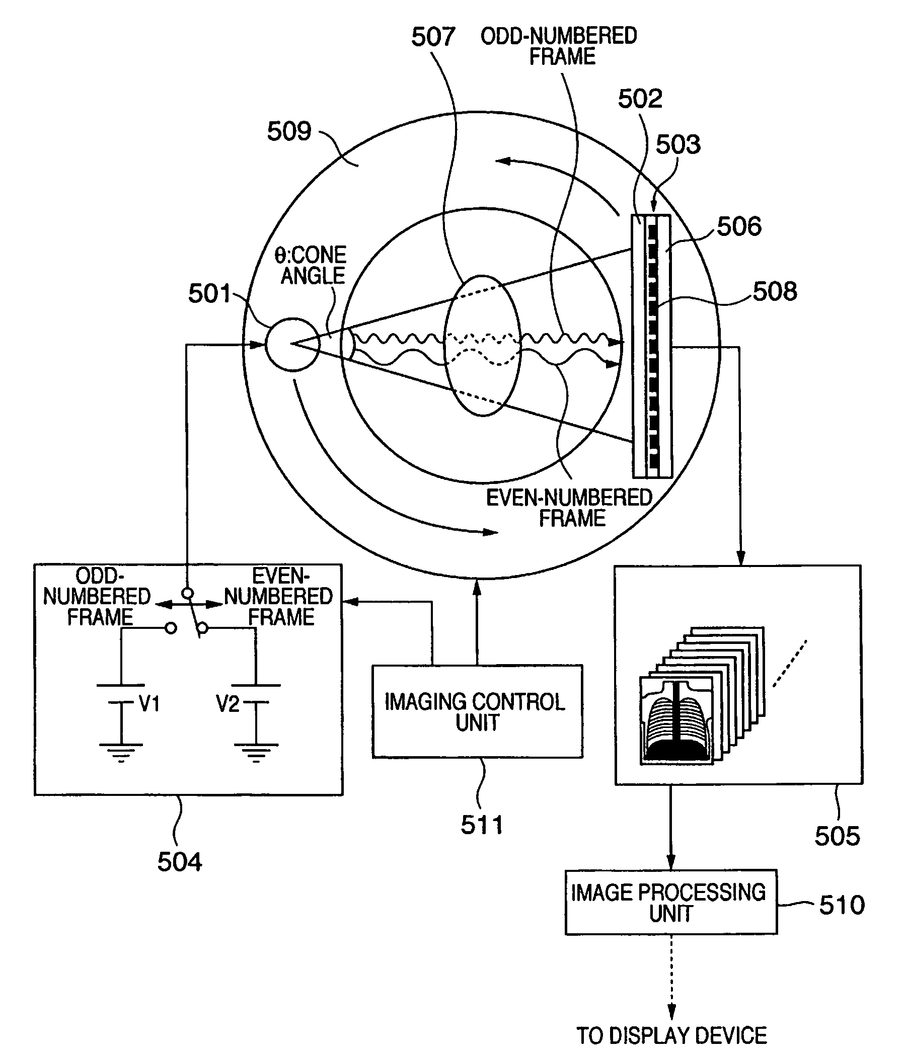
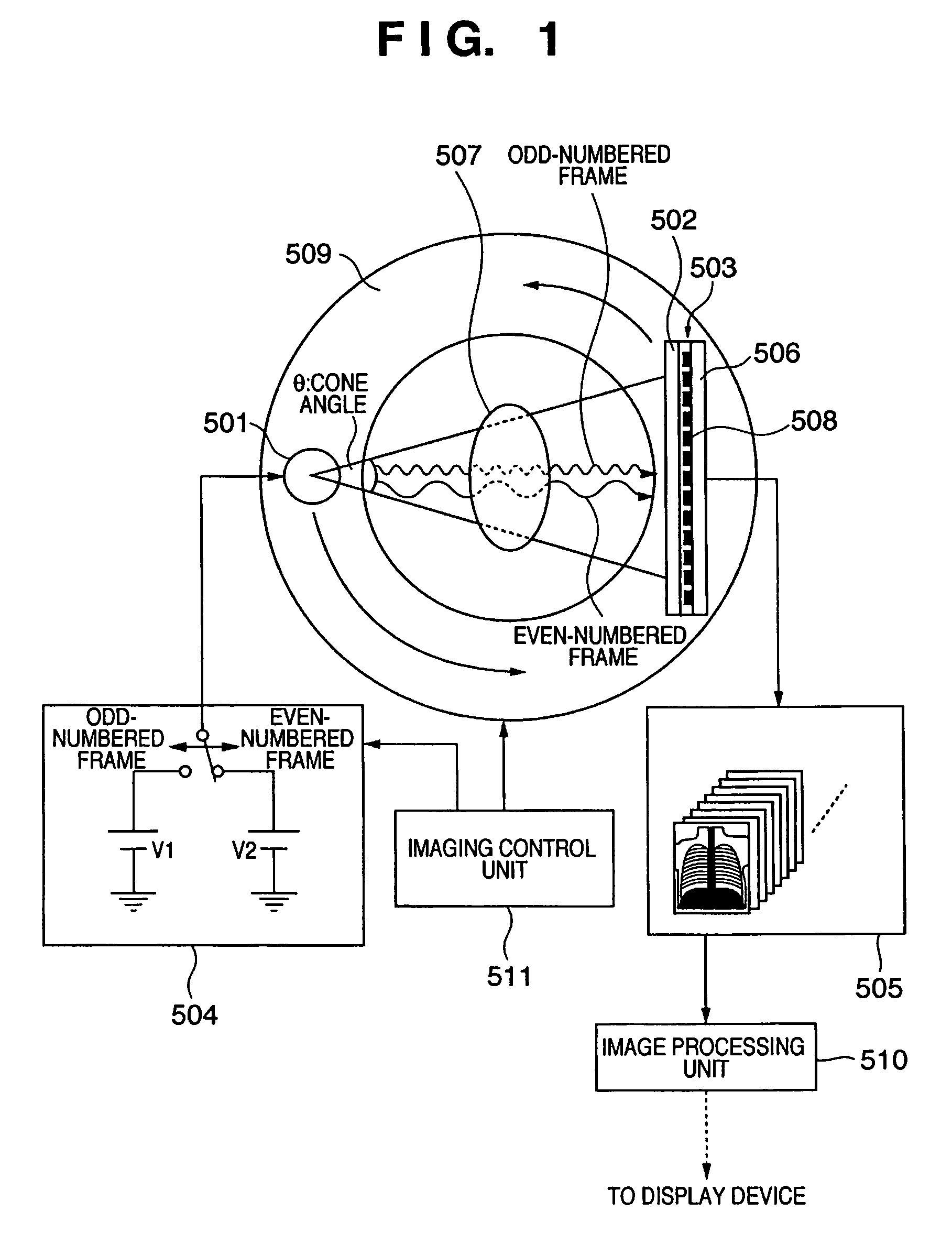
[0039]FIG. 1 is a view showing the schematic arrangement of an X-ray imaging apparatus according to the preferred first embodiment of the present invention.

[0040]An object 507 is irradiated with X-rays which are emitted from an X-ray tube 501 and have an exit angle θ. The object 507 is mainly a human (patient). The X-rays transmitted through the object 507 are converted into visible light by a phosphor 502. The visible light from the phosphor 502 is converted into an electrical signal by conversion elements 508. As a result, an X-ray image of the object 507 is obtained as an electrical signal.

[0041]An example of the material of the conversion elements 508 is amorphous silicon. The conversion elements 508 are formed on an insulating substrate 506 such as a glass substrate. The phosphor 502 to convert X-rays into visible light and the conversion elements 508 substantially adhere to each other by, e.g., bonding or the like so that an X-ray detection circuit 503 including the phosphor 5...

second embodiment

[0103]FIG. 11 is a view showing the schematic arrangement of an X-ray imaging apparatus according to the preferred second embodiment of the present invention.

[0104]An object 507 is irradiated with X-rays which are emitted from an X-ray tube 501 and have an exit angle θ. The object 507 is mainly a human (patient). The X-rays transmitted through the object 507 are converted into visible light by a phosphor 502. The visible light from the phosphor 502 is converted into an electrical signal by conversion elements 508. As a result, an X-ray image of the object 507 is obtained as an electrical signal.

[0105]An example of the material of the conversion elements 508 is amorphous silicon. The conversion elements 508 are formed as pixels on an insulating substrate 506. The phosphor 502 and conversion elements 508 substantially adhere to each other by, e.g., bonding or the like so that an X-ray detection circuit 503 including the phosphor 502 and conversion elements 508 is formed. The phosphor ...

third embodiment

[0112]FIG. 13 is a timing chart showing the operation of an X-ray imaging apparatus according to the preferred third embodiment of the present invention. The timing chart in FIG. 13 shows four signals: “move”, “X-rays”, “tube voltage” and “picture signal” in radiographing odd- and even-numbered frames. “Move” indicates the timing of rotation (displacement) of an object 507 which is arranged between an X-ray tube 501 and an X-ray detection circuit 503. As a characteristic feature of the third embodiment, the reading operation is executed in accordance with a sequence wherein movement is done in odd-numbered frame radiography but not in even-numbered frame radiography. Radiography is executed with one rotation for every two frames. More specifically, an imaging control unit 511 shown in FIG. 11 does not change the positional relationship between the object 507 and the X-ray tube 501 and X-ray detection circuit 503 in odd-numbered frame radiography for the (2m−1)th frame and even-numbe...


PUM

PropertyMeasurementUnit
sizeaaaaaaaaaa
sizeaaaaaaaaaa
rotation angleaaaaaaaaaa

Abstract

A radiographic imaging apparatus includes a radiation detection circuit with elements arranged two-dimensionally to convert radiation into an electrical signal, a driving mechanism which changes a positional relationship between the components, a memory which stores that electrical signal, an imaging controller to control the radiation source so as to emit a first radiation pulse at a first energy for a first frame and to emit a second radiation pulse at a second energy for a second frame, controlling the driving mechanism to maintain the positional relationship during the first radiation pulse and the second radiation pulse and to change the positional relationship in a period between the first period and the second period. The frames are different and sequentially imaged, and an image processing unit for subtraction processing of the first and second frames in memory to generate a processed image, then generate a tomographic and a 3D image.

Description

FIELD OF THE INVENTION[0001]The present invention relates to a radiographic imaging apparatus, a control method thereof, and a radiographic imaging system.BACKGROUND OF THE INVENTION[0002]Conventional X-ray imaging systems installed in hospitals are classified into film radiography and digital radiography. In film radiography, a patient is irradiated with X-rays, and the X-rays that have passed through the patient are exposed to a film. In digital radiography, X-rays that have passed through a patient are converted into an electrical signal, and the electrical signal is detected as a digital value by using an A / D converter and stored in a memory.[0003]An example of the current mainstream of the latter digital radiography is disclosed in Japanese Patent Laid-Open No. 5-224322. In this scheme, an X-ray image is formed on a photostimulable phosphor called an imaging plate (IP) using BaBr:Eu as a typical material. Then, the IP is scanned with a laser beam, and visible light from the IP ...

Claims


Application Information

Patent Timeline
Patent Type & Authority Patents(United States)
IPC IPC(8): H05G1/60G01N23/00
CPCA61B6/482A61B6/032A61B6/0478A61B6/405A61B6/463A61B6/4035
Inventor ENDO, TADAOKAMESHIMA, TOSHIOYAGI, TOMOYUKITAKENAKA, KATSUROYOKOYAMA, KEIGO
Owner CANON KK
Why Eureka
Try Eureka