Piping connector

a technology of piping connectors and connectors, applied in couplings, combustion air/fuel air treatment, machines/engines, etc., can solve the problems of extremely large inserting resistance, reduce the radius of curvature, and reduce the inserting resistan

Active Publication Date: 2008-06-17
PIOLAX CO LTD
View PDF21 Cites 66 Cited by
  • Summary
  • Abstract
  • Description
  • Claims
  • Application Information

AI Technical Summary

Benefits of technology

[0026]According to the invention, the peak of the inserting resistance generated in a procedure in which the seal ring passes the radius portion from the first taper portion and rides on the flat portion can be lowered. That is, the smaller the radius of curvature of the radius portion, the higher the inserting resistance of the seal ring and the larger the radius of curvature of the radius portion, the lower the inserting resistance by the seal ring.
[0027]Further, by lowering the inserting resistance by the seal ring, the inserting resistance as a whole is lowered, a reduction at an interval between the peak of the inserting resistance by the seal ring and the peak of the inserting resistance by the stopper can be reduced and it can further effectively be prevented that an operator stops insertion in the midst of the connection by erroneously recognizing that the connection has been finished to thereby bring about connecting failure.

Problems solved by technology

However, according to the piping connector of the prior art, in a procedure of inserting the plug into the socket, before the seal ring passes a portion of shifting from the first taper portion to the flat portion, the diameter of the stopper is expanded while being brought into contact with the second taper portion and therefore, there poses a problem that an inserting resistance becomes extremely large.
Since the inserting resistance is large as described above, the plug needs to be pressed into the socket by a strong force, which may constitute a hindrance when operation is carried out by putting the hand into a narrow gap arranged with an engine of an automobile or the like.

Method used


Image

  • Piping connector
  • Piping connector
  • Piping connector

Examples


Embodiment Construction

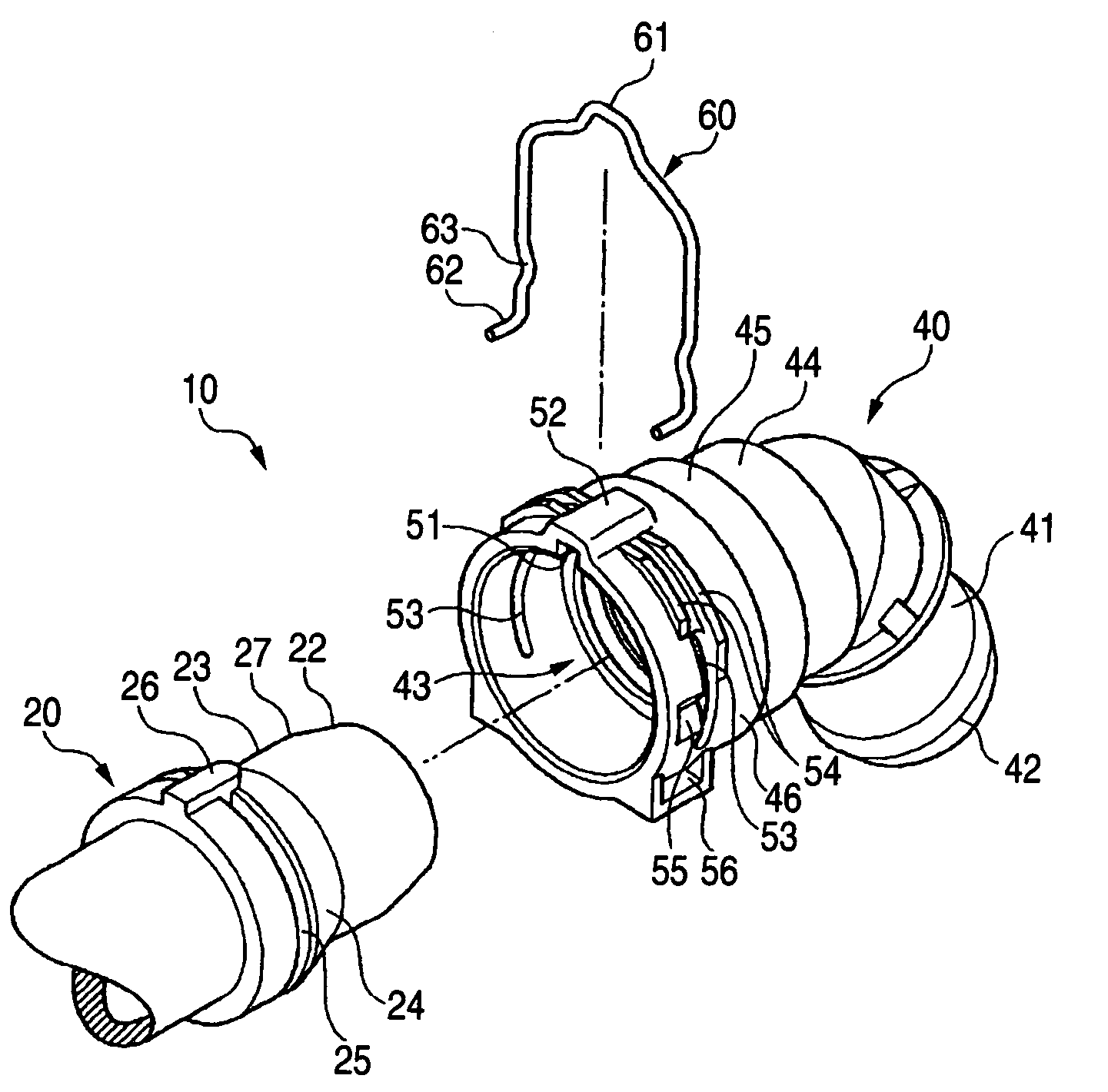
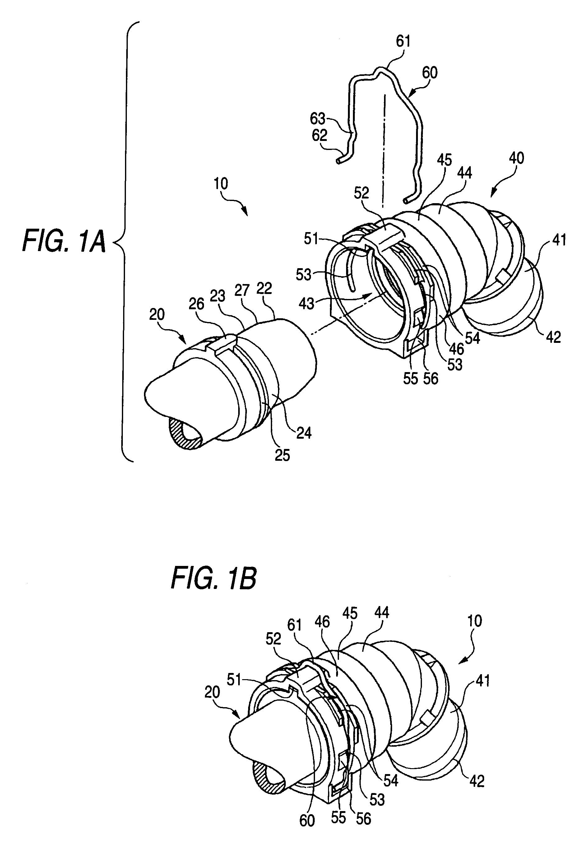
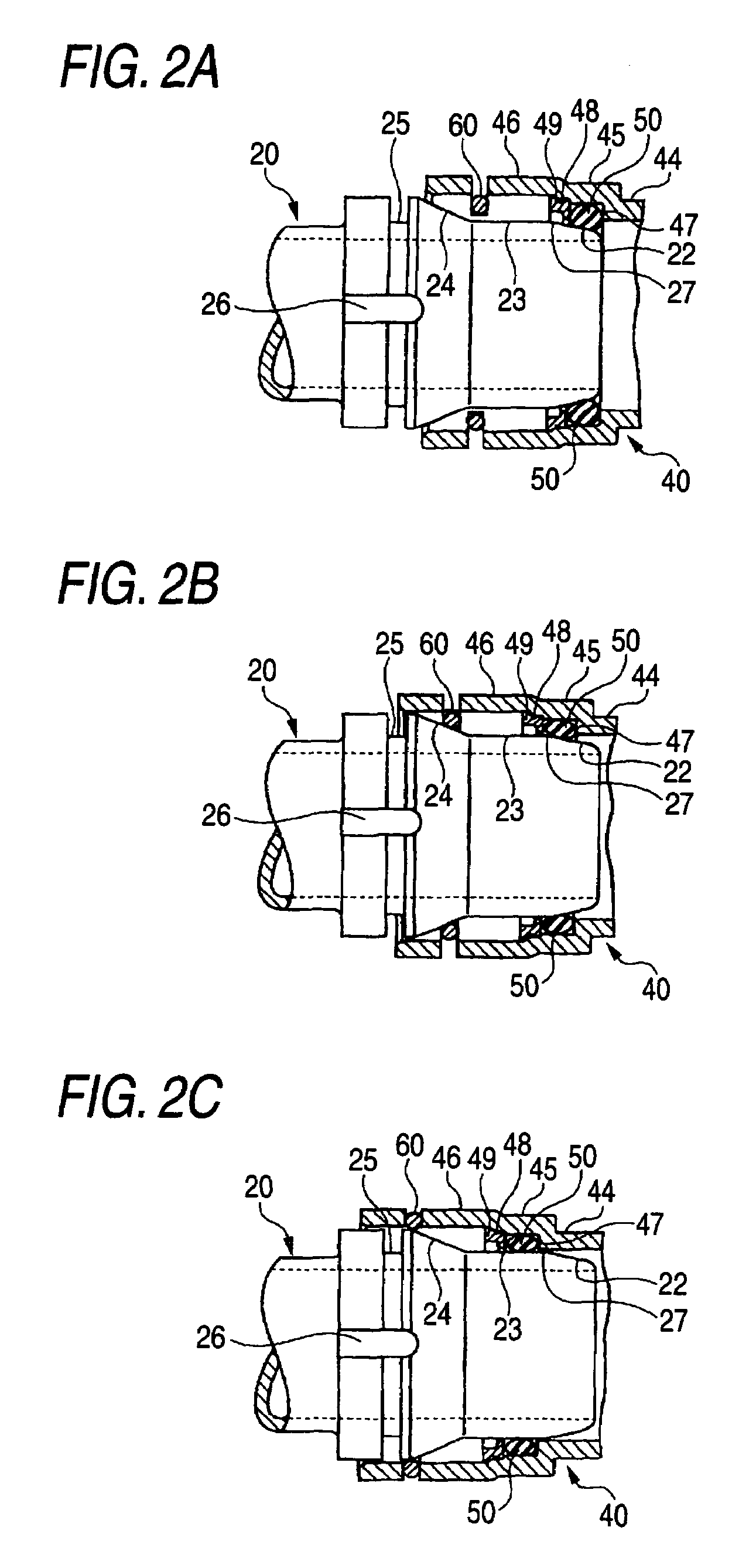
[0034]FIGS. 1A through 3B show an embodiment of a piping connector of the invention. FIGS. 1A and 1B illustrate perspective views of the connector, FIG. 1A is a disassembled perspective view, FIG. 1B is a perspective view showing a connected state, FIGS. 2A to 2C illustrate explanatory views showing a procedure of inserting a plug of the connector into a socket to connect, FIG. 2A is a view showing a state in which a first taper portion starts to be inserted into a seal ring, FIG. 2B is an explanatory view showing a state in which the seal ring passes a radius portion from the first taper portion to ride over the flat portion, FIG. 2C is an explanatory view showing a state in which a stopper rises on a second taper portion, FIGS. 3A and 3B illustrate explanatory views showing a relationship between an inserted position and an inserting resistance of the plugged connector, FIG. 3A is an enlarged side view of the plug, and FIG. 3B is a diagram showing a relationship between the insert...


PUM


Abstract

A socket is attached to an end of one pipe and a plug is attached to an end of another pipe. The socket is provided with a pair of notched grooves at peripheral faces on both sides opposed to each other and a stopper constituting a U-shape is mounted onto the notched groove. The plug is provided with a first taper portion, a flat portion, and a second taper portion continuously from a front end side thereof in a sectional shape thereof along an axial direction, and a groove having the stopper inserted therein is formed at a ridge portion of the second taper portion. An inner periphery of the socket is arranged with a seal ring for sealing an interval between the inner periphery of the socket and an outer periphery of the plug in an airtight connection.

Description

BACKGROUND OF THE INVENTION[0001]1. Field of the Invention[0002]The present invention relates to a piping connector preferably used in a fluid pipe in, for example, a cooling system or an intake system of an engine of an automobile.[0003]2. Description of the Related Art[0004]In connecting to, for example, a radiator hose or the like of an automobile, there is widely utilized a piping connector (pipe joint) made to be connected in one touch motion by only inserting a plug attached to an end portion of other pipe into a socket attached to an end portion of one pipe.[0005]For example, in JP-A-10-9470, there is disclosed such a piping connector in which an outer peripheral groove is provided at an outer periphery of a female pipe (socket), the outer peripheral grove is provided with notched grooves penetrating inner and outer diameters and opposed to each other by a necessary angle, a stop piece arm (stopper) is engaged with a valley peripheral diameter portion of an unnotched groove p...

Claims


Application Information

Patent Timeline
Patent Type & Authority Patents(United States)
IPC IPC(8): F16L37/088F16L37/12F16L21/00F16L37/14
CPCF16L37/088F02M35/10144F01P11/04F16L37/0885
Inventor YOSHIDA, NAOKI
Owner PIOLAX CO LTD
Why Eureka
Try Eureka