Electron microscope

a technology of electron microscope and electron microscope, applied in the field of electron microscope, can solve problems such as difficulty in displaying eels profiles at high speed

Inactive Publication Date: 2008-06-17
JEOL LTD
View PDF13 Cites 4 Cited by
  • Summary
  • Abstract
  • Description
  • Claims
  • Application Information

AI Technical Summary

Benefits of technology

[0013]Accordingly, the present invention can provide an electron microscope capable of obtaining an EELS profile irrespective of the beam position on the specimen.

Problems solved by technology

However, this surface analysis using EELS produces the following problems: (1) When the electron beam scans over the specimen surface, the spectral position on the CCD camera is moved.
Since the image recognition processing is time-consuming, it has been heretofore difficult to display EELS profiles at high speed.

Method used


Image

  • Electron microscope
  • Electron microscope
  • Electron microscope

Examples


Embodiment Construction

[0022]The preferred embodiments of the present invention are hereinafter described with reference to the accompanying drawings.

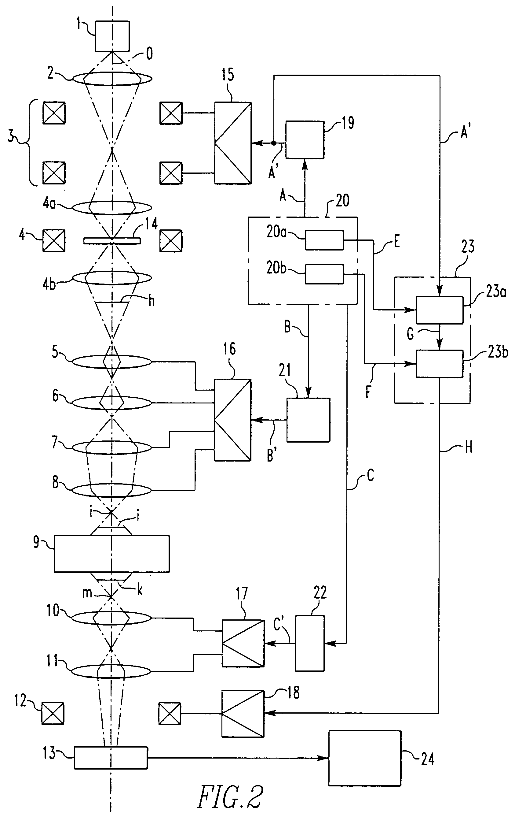
[0023]FIG. 2 shows a transmission electron microscope according to the present invention. The microscope has an electron gun 1. A condenser lens 2, two stages of scan coils (first deflector) 3, an objective lens 4, four stages of intermediate lenses 5-8, an Omega filter (energy filter) 9, two stages of projector lenses 10, 11, a deflection coil (second deflector) 12 for moving the spectral position, and a CCD camera (image detector) 13 are placed in this order from the gun side behind the gun 1. A specimen 14 is set on a specimen holder (not shown) and positioned between the front electric field 4a and rear electric field 4b of the objective lens 4.

[0024]Referring also to FIG. 2, there are shown an amplifier (drive power supply) 15 for driving the scan coils 3, an amplifier 16 for driving the intermediate lenses 5-8, an amplifier 17 for driving the projector...


PUM


Abstract

An electron microscope capable of producing EELS (electron energy-loss spectroscopy) has a spectral position correcting signal supply circuit for supplying a spectral position correcting signal H to a first driver amplifier to project spectra at the center of a CCD camera. This correcting signal H corresponds to a beam deflection signal A′ supplied from a scan generator to a second driver amplifier, an excitation signal B′ supplied from an intermediate lens excitation signal supply circuit to a third driver amplifier, and another excitation signal supplied from a projector lens excitation signal supply circuit to a fourth driver amplifier.

Description

BACKGROUND OF THE INVENTION[0001]1. Field of the Invention[0002]The present invention relates to an electron microscope capable of analyzing the electronic state of a solid specimen by electron energy-loss spectroscopy (EELS).[0003]2. Description of Related Art[0004]When incident electrons collide against atoms constituting a solid specimen, some of the electrons interact with electrons within the specimen crystal or crystal lattice, lose part of their energy, and are scattered, that is, their velocity decreases. These scattered electrons are known as inelastically scattered electrons. A technique for analyzing the electronic state of a solid specimen by analyzing inelastically scattered electrons in terms of energy is known as electron energy-loss spectroscopy (EELS). On the other hand, when incident electrons collide against atoms constituting a solid specimen and scatter without losing energy, the electrons are termed elastically scattered electrons.[0005]In the current electron ...

Claims


Application Information

Patent Timeline
Patent Type & Authority Patents(United States)
IPC IPC(8): G21K7/00H01J37/256
CPCH01J37/256H01J2237/24455H01J2237/2538
Inventor OHKURA, YOSHIHIRO
Owner JEOL LTD
Why Eureka
Try Eureka