Stent crimping system

a crimping system and stent technology, applied in the field of intraluminal devices, can solve the problems of uneven radial crimping force applied to the stent, stents that are not properly crimped, secured or retained to the delivery catheter may slip and be lost, and achieve the effect of increasing reducing the size of the crimp apertur

Active Publication Date: 2008-06-24
ABBOTT LAB INC
View PDF94 Cites 45 Cited by
  • Summary
  • Abstract
  • Description
  • Claims
  • Application Information

AI Technical Summary

Benefits of technology

[0010]The present invention provides an apparatus and methods for mechanically crimping a generally tubular stent from a first diameter to a second diameter. A stent crimping assembly is provided that includes a plurality of movable wedges having respective first side and a second side converging to form a tip portion. The tip portions are arranged to collectively form an iris about a rotational axis thereof. The iris defines a crimp aperture ab

Problems solved by technology

Stents that are not properly crimped, secured or retained to the delivery catheter may slip and will either be lost, be deployed in the wrong location or only be partially deployed.
In the past, crimping has been performed by hand, often resulting in an undesirable application of uneven radial crimping forces to the stent.
Stents that have been crimped multip

Method used


Image

  • Stent crimping system
  • Stent crimping system
  • Stent crimping system

Examples


Embodiment Construction

[0053]While the present invention will be described with reference to a few specific embodiments, the description is illustrative of the invention and is not to be construed as limiting the invention. Various modifications to the present invention can be made to the preferred embodiments by those skilled in the art without departing from the true spirit and scope of the invention as defined by the appended claims. It will be noted here that for a better understanding, like components are designated by like reference numerals throughout the various figures.

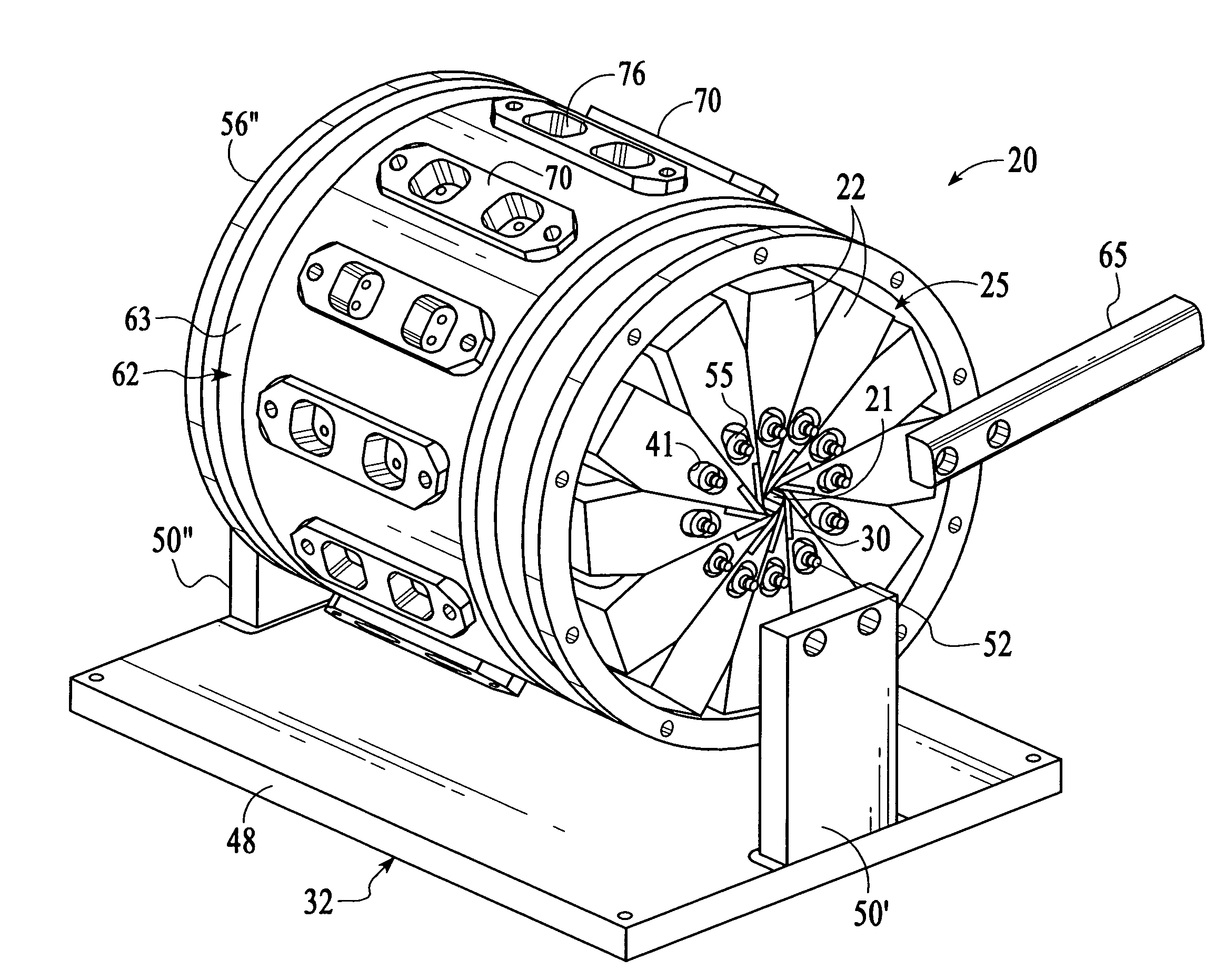
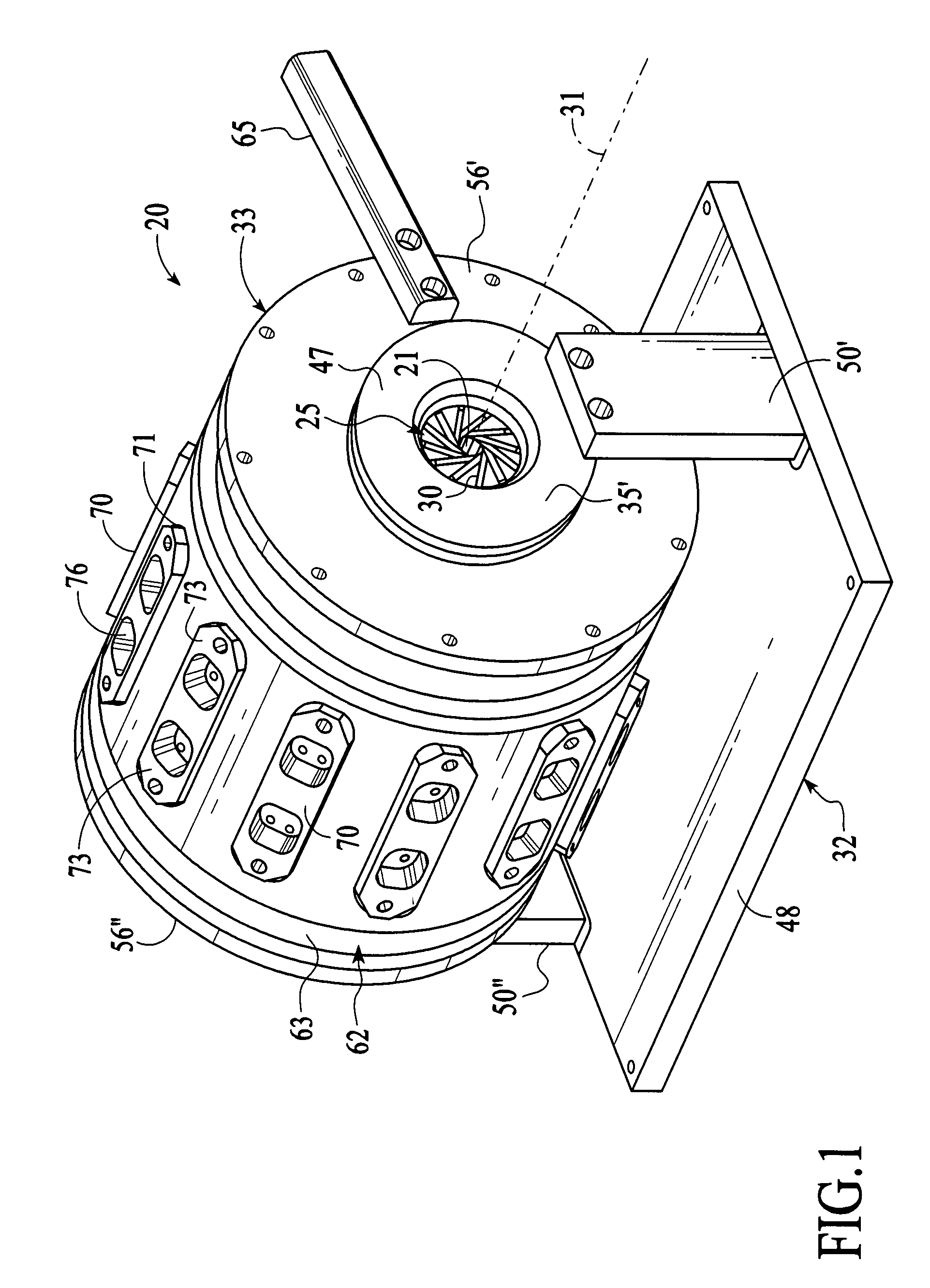
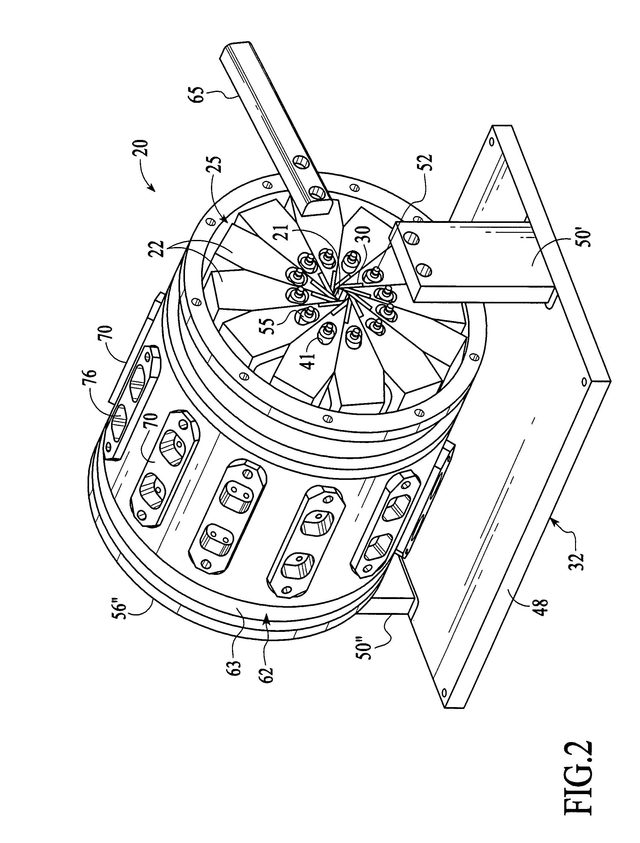
[0054]Referring now to FIGS. 1-6, a stent crimping assembly, generally designated 20, is illustrated that defines a crimp aperture 21 for crimping a stent (not shown) from a first diameter (FIG. 4) to a reduced second diameter (FIG. 5). This crimping assembly 20 includes a plurality of movable blades or wedges 22 arranged in an assembly 25 around the crimp aperture 21. Each wedge, as best viewed in FIGS. 3 and 6, include a first si...


PUM

PropertyMeasurementUnit
Diameteraaaaaaaaaa
Sizeaaaaaaaaaa
Displacementaaaaaaaaaa

Abstract

A stent crimping assembly is provided for crimping a stent from a first diameter to a reduced second diameter. The crimping assembly includes a plurality of movable wedges disposed about a rotational axis to form a wedge assembly. Each wedge includes a respective first side and a second side converging to form a tip portion. The tip portions are arranged to collectively form an iris about the rotational axis thereof. The iris defining a crimp aperture about which the movable wedges are disposed. Each wedge is associated with a stationary structure and an rotational actuation unit such that during rotation of the actuation unit about the rotational axis, the iris is caused to rotate about the rotational axis, relative the stationary structure, for inward movement of the wedges to decrease the size of the aperture and outward movement of the wedges to increase the size of the aperture.

Description

RELATED APPLICATION DATA[0001]The present application claims priority under 35 U.S.C. §119 to U.S. Provisional Application Ser. No. 60 / 591,260, naming Lowe et al. inventors, filed Jul. 26, 2004, and entitled CRIMPING APPARATUS, the entirety of which is incorporated herein by reference for all purposes.FIELD OF THE INVENTION[0002]The present invention relates generally to intraluminal devices, and more particularly relates to apparatus and methods for reducing the size of these devices, such as a stent, stent-graft, graft or vena cava filter, for percutaneous transluminal delivery thereof.BACKGROUND OF THE INVENTION[0003]A number of vascular diagnostic and interventional medical procedures are now performed translumenally. For example, catheter is introduced to the vascular system at a convenient access location and guided through the vascular system to a target location using established techniques. Such procedures require vascular access, which is usually established during the wel...

Claims


Application Information

Patent Timeline
IPC IPC(8): B21D41/04
CPCA61F2/95B25B27/10A61F2002/9522Y10T29/49865Y10T29/49764A61F2/9522A61F2/9524
Inventor KOKISH, ARKADYLOWE, DAVIDSHUMER, DANBARON, SCOTT
Owner ABBOTT LAB INC
Why Eureka
Try Eureka