
Apparatus and method for mechanical caliper measurements during drilling and logging-while-drilling operations

a mechanical caliper and caliper technology, applied in the field of drilling tools, can solve the problems of limited pulse-echo methods currently in use, degraded pulse-echo measurement quality, and limited technique practical limitations

Active Publication Date: 2008-06-24
BAKER HUGHES INC
View PDF15 Cites 37 Cited by
  • Summary
  • Abstract
  • Description
  • Claims
  • Application Information

AI Technical Summary

Benefits of technology

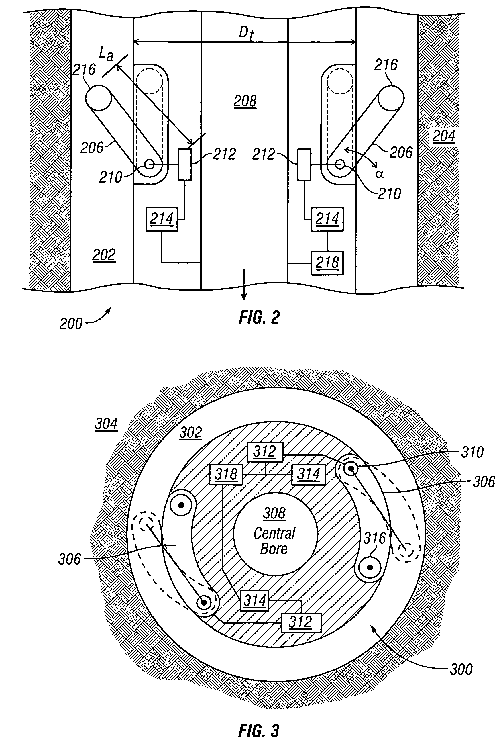
The present invention provides a tool for measuring the caliper of a borehole while drilling, reaming, and tripping the tool from the borehole. The tool includes an elongated tubular with a cutting tool for cutting into an earth formation, and a selectively extendable member that is coupled to the tool and remains decoupled from the borehole wall. A sensor is operatively associated with the extendable member and provides an output signal relating to the distance between the distal end of the extendable member and the borehole wall and the amount of extension of the extendable member. The sensor can be an ultrasonic device or a roller that allows for sliding or rolling contact with the borehole wall. The invention also includes a method for determining the borehole dimension and a system for determining the borehole dimension during drilling operations. The processed output signal is indicative of the borehole dimension.

Problems solved by technology

Caliper measurements while drilling are typically performed using ultrasonic techniques, because a rotating or longitudinally moving drill string poses problems not seen in wireling applications.
The acoustic pulse-echo methods currently in use are limited in terms of hole size coverage, and in some cases the quality of pulse-echo measurements is degraded due to incompatible return fluid and / or poor formation conditions.
This technique has practical limitations.
In order to insert the apparatus in the borehole, the drillstring must be removed, resulting in additional cost and downtime for the driller.
Such mechanical apparatus are also limited in the range of diameter measurement they provide.
Furthermore, these mechanical wireline tools are not suited or a while-drilling environment, because the arms are coupled to the borehole wall when extended.
If such a wireline tool were simply incorporated into a while-drilling system, the mechanical arm(s) will be damaged or will break.
In some cases, such a tool might damage the borehole wall making any measurement invalid.
Wireline caliper tools are also time-consuming.
In view of the excessive time costs in drilling operations, these wireline tests can be quite expensive.
Moreover, wireline tools cannot be effectively used in boreholes highly deviated from the vertical, which is often the case in directional drilling.
These tools, however suffer from other problems.
Ultrasonic tools housed in a tool collar have difficulty when measuring through some borehole fluids.
Depending upon the fluid chemistry, viscosity and the presence of particulates, the measurements may be inaccurate or impossible.
Furthermore, these highly complex tools are quite expensive and prone to failure during operation in the harsh borehole environment.

Method used


Image

  • Apparatus and method for mechanical caliper measurements during drilling and logging-while-drilling operations
  • Apparatus and method for mechanical caliper measurements during drilling and logging-while-drilling operations
  • Apparatus and method for mechanical caliper measurements during drilling and logging-while-drilling operations

Examples


Embodiment Construction

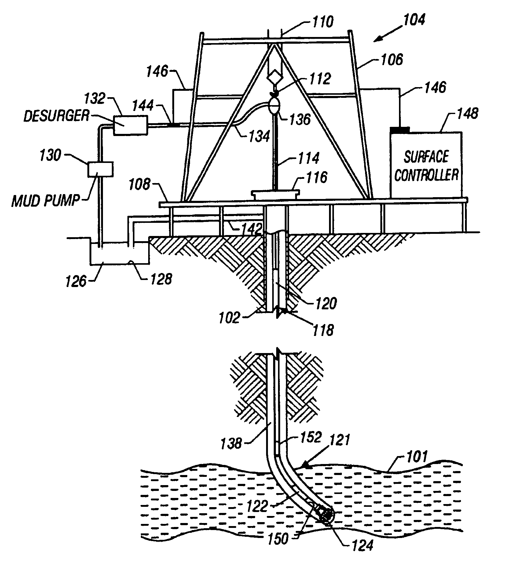
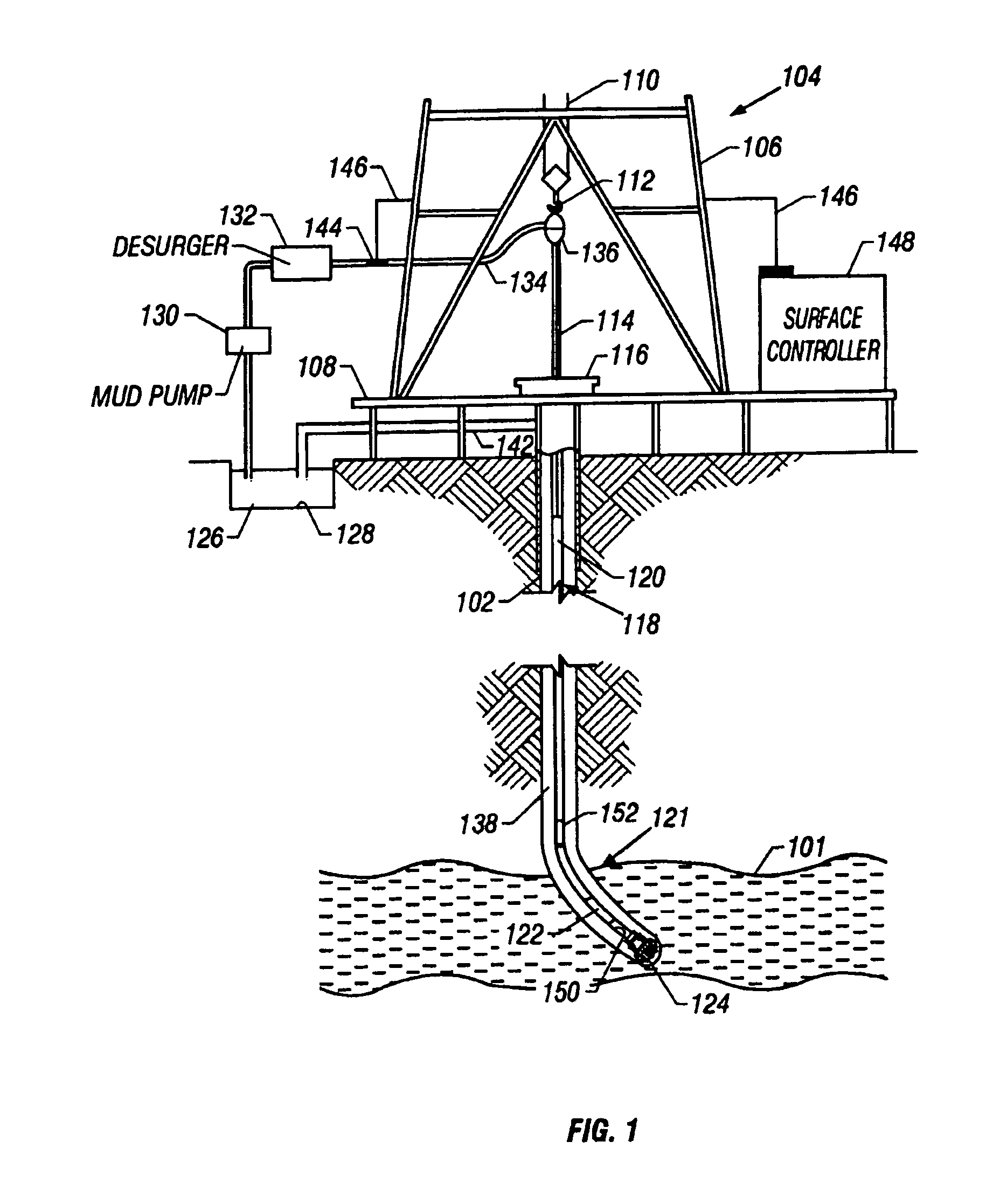
[0031]FIG. 1 is an elevation view of a simultaneous drilling and logging system that incorporates an embodiment of the present invention. A well borehole 102 is drilled into the earth under control of surface equipment including a rotary drilling rig 104. In accordance with a conventional arrangement, rig 104 includes a derrick 106, derrick floor 108, draw works 110, hook 112, kelly joint 114, rotary table 116, and drill string 118. The drill string 118 includes drill pipe 120 secured to the lower end of kelly joint 114 and to the upper end of a section comprising a plurality of drill collars. The drill collars include not separately shown drill collars such as an upper drill collar, an intermediate drill collar, and a lower drill collar bottom hole assembly (BHA) 121 immediately below the intermediate sub. The lower end of the BHA 121 carries a downhole tool 122 of the present invention and a drill bit 124.

[0032]Drilling mud 126 is circulated from a mud pit 128 through a mud pump 1...


PUM


Abstract

A caliper tool used on a drilling tubular and having extensible members that remain decoupled with respect to the borehole wall during caliper measurements and while the extensible members are extended to allow movement in and through the borehole. A processor processes known and measured information to determine the size and shape of the borehole. Formation evaluation instruments may be included to allow formation evaluation substantially simultaneously with the caliper measurements.

Description

CROSS REFERENCE TO RELATED APPLICATION[0001]This application takes priority from U.S. Provisional Patent Application Ser. No. 60 / 648,486, filed on Jan. 31, 2005.BACKGROUND OF THE INVENTION[0002]1. Field of the Invention[0003]This invention relates generally to drilling tools and in particular to an apparatus and method for determining the caliper of a well borehole while drilling, tripping or reaming.[0004]2. Description of the Related Art[0005]Many well logging and formation measurement applications require knowledge of the caliper of the borehole. Caliper measurements are typically performed using a wireline caliper tool run into the borehole after tripping the drill string. Caliper measurements while drilling are typically performed using ultrasonic techniques, because a rotating or longitudinally moving drill string poses problems not seen in wireling applications.[0006]Accurate borehole size and geometry information is needed for a large range of applications. Data quality asse...

Claims


Application Information

Patent Timeline
Patent Type & Authority Patents(United States)
IPC IPC(8): E21B47/08
CPCE21B47/08E21B47/082E21B47/085
Inventor RITTER, RENEFREITAG, HANS-CHRISTIANFABER, HANS-JUERGENKINNEY, JAMES
Owner BAKER HUGHES INC
Learn More