Fretting and whisker resistant coating system and method

a technology of whisker and coating system, applied in the direction of surface reaction electrolytic coating, non-conductive material with dispersed conductive material, solid-state devices, etc., can solve the problems of reducing the performance of electrical devices, reducing the wettability of solder, and easy oxidation and tarnish, so as to minimize the increase of resistivity

Active Publication Date: 2008-06-24
WIELAND ROLLED PROD NORTH AMERICA LLC
View PDF55 Cites 37 Cited by
  • Summary
  • Abstract
  • Description
  • Claims
  • Application Information

AI Technical Summary

Benefits of technology

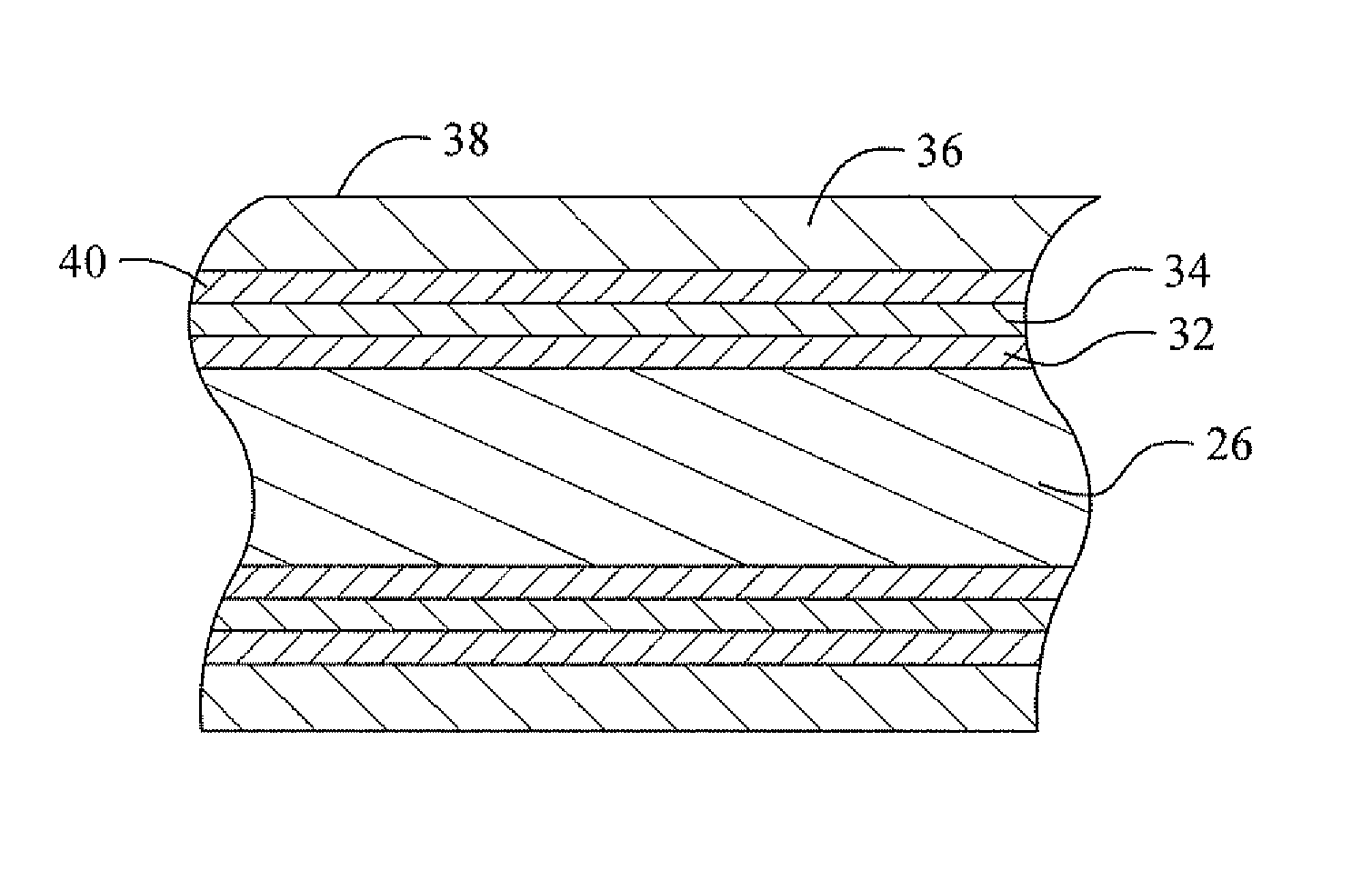
[0017]In accordance with a second embodiment of the invention, there is provided a coated electrically conductive substrate having particular utility where the debris from fretting wear may oxidize and increase electrical resistivity, such as in a connector assembly. The electrically conductive substrate has a barrier layer deposited on the substrate that is effective to inhibit diffusion of constituents of the substrate into a plurality of subsequently deposited layers. The subsequently deposited layers include a sacrificial layer deposited on the barrier layer that is effective to from intermetallic compounds with tin, a metal that is capable of forming a low resistivity oxide (referred to herein as a “low resistivity oxide metal layer”) deposited on said sacrificial layer, and an outermost layer of tin or a tin-base alloy directly deposited on the low resistivity oxide metal layer
[0020]It is believed that this silver-rich phase is particularly beneficial to minimize an increase in resistivity due to oxidation of fretting wear debris.

Problems solved by technology

While copper provides excellent electrical conductivity, it is known to easily oxidize and tarnish when exposed to elevated temperatures, moisture, or chemicals.
Oxidation and tarnishing of copper generally result in high electrical contact resistance, thereby reducing performance of electrical devices.
In addition, oxidation and tarnishing of copper reduce the wettability of solder, and generally makes soldering problematic.
However, there are many problems associated with using tin as a coating layer on a conductive substrate.
One approach taken to reduce the effect of IMC formation and maintain a low contact resistance is to use a thicker tin coating; however, this approach not only increases the cost of the parts but also causes some functional problems.
Where the tin coating is used on an electrical connector, a thicker coating of soft tin increases friction leading to an increased insertion force, making plugging and unplugging the connector physically difficult.
For electronic devices, a thicker tin or tin alloy coating is also undesirable since the trend is to make electronic devices thinner and smaller.
Moreover, where the tin coating is used on leads of an electronic device, a thick tin coating can cause problems in the coplanarity and fine line definition of the leads.
However, this example was shown to be undesirable because the silver transition barrier layer resulted in no substantial reduction in the diffusion rate between copper and tin.
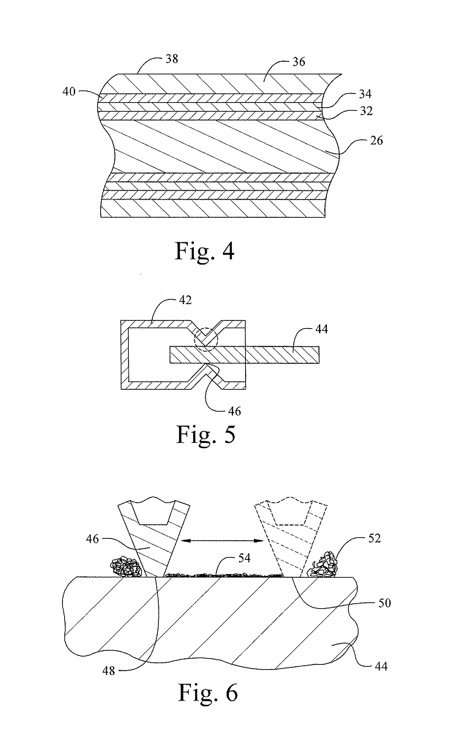
Another problem associated with the use of tin as a coating layer for a conductive substrate is that tin is susceptible to fretting corrosion.
The oxidation caused by fretting can result in an unacceptable increase in contact resistance.
However, silver tends to tarnish in the atmosphere due to the presence of sulfur dioxide, which causes silver sulfide to form on the surface of the silver.
The tarnish is aesthetically unacceptable and could degrade the functional properties of the electrical contact.
Yet another problem associated with the use of a tin coating layer, as well as other coating layers such as zinc, indium, antimony, or cadmium, on a conductive substrate is that tin is susceptible to whiskering.
Whiskering also occurs due to internal stress resulting from the plating process.
Whiskering can cause many different problems, including shorting of adjacent electrical contact surfaces.

Method used


Image

  • Fretting and whisker resistant coating system and method
  • Fretting and whisker resistant coating system and method
  • Fretting and whisker resistant coating system and method

Examples


example 1

Tin Whiskering

[0075]Coupons 2 inches×0.5 inch×0.010 inch thick were cut from a strip of copper alloy C194. Copper alloy C194 has a composition by weight of 2.1% / -2.6% iron, 0.05%-0.20% zinc, 0.015%-0.15% phosphorous and the balance is copper. The coupons were cleaned in a commercial alkaline cleaner at 50° C. using a cathodic current density of 15 asf (amps per square foot) for 1 minute.

[0076]Referring to Table 2, when a nickel layer was deposited, deposition was by electroplating. The Ni plating solution was an aqueous solution containing from about 60 to 75 g / l (grams per liter) Ni as Ni sulfamate, about 6 to 8 g / l NiCl2, and about 38 to 53 g / l boric acid at 53° C. with a pH between about 3.5 and 4.2. The Ni plating conditions were 30 asf for about 60 seconds.

[0077]When a copper layer was deposited, deposition was by electroplating from an aqueous solution containing about 20 to 70 g / l Cu and about 50 to 200 g / l H2SO4 at 40-60° C. using a current density of 40 asf for about 40 sec...

example 2

Fretting Wear Impact on Contact Resistance

[0083]Coupons having the dimensions 6 inches by 1.25 inches by 0.005 inch were formed from copper alloys C194 and C7025, has a composition, by weight, of 2.2%-4.2% nickel, 0.25%-1.2% silicon, 0.05%-0.3% Mg and the balance is copper.

[0084]The copper alloy coupons were coated with intervening layers and matte tin as in Example 1 except that the silver layer was deposited by the immersion method using MacDermid Sterling™ silver solution and the tin was deposited from a sulfate solution containing 20 g / l to 80 g / l of tin ions as SnSO4 50 g / l to 200 g / l sulfuric acid, and organic additives.

[0085]The impact of fretting wear on contact resistance was determined by moving a ¼″ diameter bump at 5 Hz up to 20,000 cycles with a cycle length of 20 μm across a contact surface to be tested. A normal force of 100 g was applied to the bump, and contact resistance data was collected while the bump was in motion. The values reported are the number of cycles ...

example 3

Coefficient of Friction

[0090]Copper alloy C194 coupons having the dimensions 6 inch×1.25 inch×0.005 inch were coated with intervening layers and matte tin as in the preceding examples. A reflowed tin surface was obtained by heating a sample to 350° C. in air and quenching in water.

[0091]The coefficient of friction was measure as the ratio of the resistive force relative to the normal force (R / N) when a ¼ inch diameter bump slid at 3 mm / sec for 10 cycles across a tin coated flat surface. The normal force was loaded as dead weight and no lubricant was applied between the tin coated surface and the bump. The resistive force was measured as the bump was slid against the flat surface of the sample. The value reported was the average of all 10 cycles. A lower R / N indicates less friction. The results are reported in Table 4.

[0092]

TABLE 4InterveningLayers -Thickness inTinR / NμinchThickness0-60 mmSampleCuAgTin Typeμinch100 g250 g120-40-0-Matte40-800.550.55220-402-5Matte40-800.580.53320-40 5-...


PUM

PropertyMeasurementUnit
temperatureaaaaaaaaaa
thicknessaaaaaaaaaa
thicknessaaaaaaaaaa

Abstract

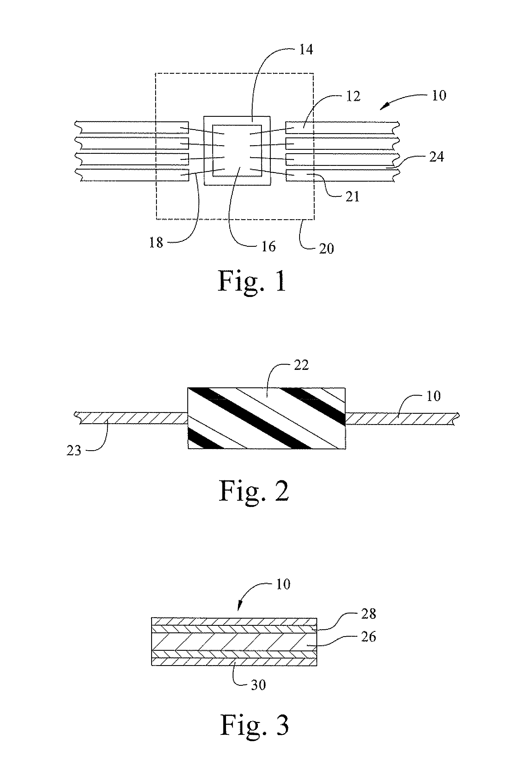
A coated electrically conductive substrate has particular utility where there are multiple closely spaced leads and tin whiskers constitute a potential short circuit. This electrically conductive substrate has a plurality of leads separated by a distance capable of bridging by a tin whisker, a silver or silver-base alloy layer coating at least one surface of at least one of the plurality of leads, and a fine grain tin or tin-base alloy layer directly coating said silver layer. An alternative coated electrically conductive substrate has utility where debris from fretting wear may increase electrical resistivity. This electrically conductive substrate has a barrier layer deposited on the substrate that is effective to inhibit diffusion of the substrate into a subsequently deposited layers, which include a sacrificial layer deposited on the barrier layer that is effective to form intermetallic compounds with tin, and a low resistivity oxide metal layer deposited on the sacrificial layer.An alternative coated electrically conductive substrate has particular utility where debris from fretting wear may oxidize and increase electrical resistivity, such an in a connector assembly. This electrically conductive substrate has a barrier layer deposited on the substrate that is effective to inhibit diffusion of constituents the substrate into a plurality of subsequently deposited layers. The subsequently deposited layers include a sacrificial layer deposited on the barrier layer that is effective to form intermetallic compounds with tin, a low resistivity oxide metal layer deposited on said sacrificial layer, and an outermost layer of tin or a tin-base alloy directly deposited on the low resistivity oxide metal layer.In this alternative embodiment, the barrier layer is preferably nickel or a nickel-base alloy and the low resisitivity oxide metal layer is preferably silver or a silver-base alloy.When heated, the coated substrate of this second embodiment forms a unique structure having a copper or copper-base alloy substrate, an intervening layer formed from a mixture or metals including copper and tin, and an outermost layer which is a mixture of a copper-tin intermetallic containing phase and a silver-rich phase. It is believed that this silver-rich phase is particularly beneficial to reduce an increase in resistivity due to oxidation of fretting wear debris.

Description

CROSS-REFERENCE TO RELATED PATENT APPLICATIONS[0001]This patent application claims priority to U.S. Provisional Patent Application Ser. No. 60 / 511,249 that was filed on Oct. 14, 2003. The subject matter of that provisional patent application is incorporated by reference in its entirety herein.BACKGROUND OF THE INVENTION[0002](1) Field of the Invention[0003]This invention relates to systems and methods for coating electrically conductive substrates, and more particularly to multi-layer systems and methods for coating electrically conductive substrates.[0004](2) Description of the Related Art[0005]Throughout this patent application, the word “base” to qualify an alloy means that the alloy contains at least 50%, by weight, of the qualified element, for example, “copper-base” means more than 50%, by weight, of copper. Copper and copper-base alloys (hereinafter generally referred to as “copper”) are commonly used in electrical and electronic industries for connectors, electrical harnesse...

Claims


Application Information

Patent Timeline
Patent Type & Authority Patents(United States)
IPC IPC(8): H01L23/48H01L23/52H01L29/40B05D3/02B32B15/08C23C2/02C23C28/02C25D5/10C25D11/02H01L23/495H01RH05K3/24
CPCC23C2/02C23C28/023C25D5/10H01L23/49582H01R13/03C23C28/021C23C28/321C23C28/322C23C28/345C23C28/025C23C28/3225C23C28/3455C23C28/347Y10T428/12896H01L2224/48247H01L2224/49171H01L2924/01012H01L2924/0102H01L2924/01025H01L2924/01046H01L2924/01063H01L2924/01078H01L2924/01079H01L2924/14H05K3/244H01L24/48H01L24/49H01L2924/01019H01L2924/01322H01L2224/11849H01L2224/119H01L2924/01327Y10T428/1259Y10T428/12715Y10T428/12611H01L2924/00H01L2224/451H01L2224/45015H01L2224/45139H01L24/45H01L2924/181C25D5/12C25D5/627C25D5/617H01L2924/207H01L2924/00014H01L2924/2075H01L2924/00012H01B1/16
Inventor CHEN, SZUCHAIN F.LASIUK, NICOLE A.GERFEN, JOHN E.ROBINSON, PETER W.KHAN, ABID A.
Owner WIELAND ROLLED PROD NORTH AMERICA LLC
Why Eureka
Try Eureka