Radio receiver/transceiver including an interface circuit selectively operable in a current mode or a voltage mode

a radio receiver and transceiver technology, applied in the field of radio receivers/transceivers, can solve the problems that transceivers operable in current mode and transceivers operable in voltage mode are unsuitable for use in wireless environments, and achieve the effects of reducing noise contribution, low gain, and improving optimisation

Inactive Publication Date: 2008-06-24
BREAKWATERS INNOVATIONS
View PDF8 Cites 10 Cited by
  • Summary
  • Abstract
  • Description
  • Claims
  • Application Information

AI Technical Summary

Benefits of technology

[0013]Embodiments can be realised in which the noise figure is between 5.6 and 6.2. This is preferable since it reduces the noise contribution of the following stages of a receiver.
[0014]Furthermore, the relatively low gain is used when the radio receiver is operable in the voltage mode. In voltage mode, the voltage gain of the mixer and first filter stage is either 24 dB or 8 dB and the second stage gain can be varied as for current mode. With the combination of current and voltage modes, the voltage gain can be varied to a number of values based on signal strength, while still at least influencing and, preferably, optimising, at least one of noise figure, linearity and current consumption. A better optimisation can be achieved than would be possible using only current or voltage mode.
[0024]In current mode, the Rf resistors cannot be reduced too much because the output of the op-amps are loaded by the resistors. Therefore, when the voltage swing at the output of the op-amp is large, the current drive of the op-amps needs to be large.

Problems solved by technology

Therefore, it will be appreciated that a transceiver operable in current mode might be unsuitable for use in a wireless environment in which relatively large signals prevail.
Similarly, a transceiver operable in voltage mode might be unsuitable for use in a wireless environment in which relatively small signals prevail.

Method used


Image

  • Radio receiver/transceiver including an interface circuit selectively operable in a current mode or a voltage mode
  • Radio receiver/transceiver including an interface circuit selectively operable in a current mode or a voltage mode
  • Radio receiver/transceiver including an interface circuit selectively operable in a current mode or a voltage mode

Examples


Embodiment Construction

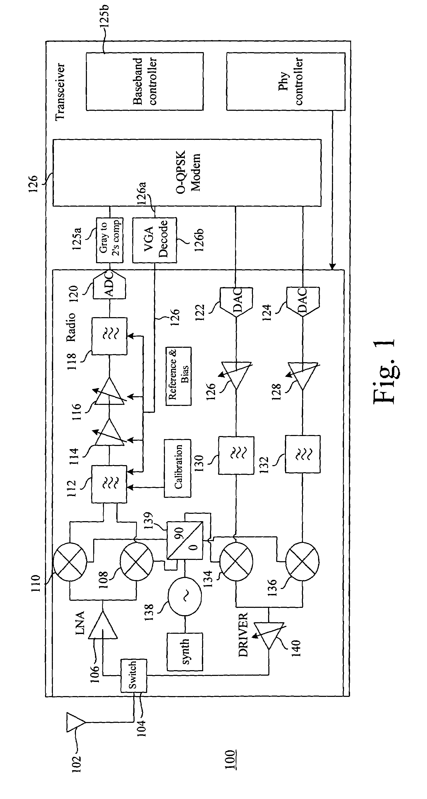
[0032]FIG. 1 shows a transceiver 100. The transceiver comprises an antenna 102 coupled to a switch 104. The switch 104 is arranged to direct a received signal to a low noise amplifier 106. The low noise amplifier 106, having amplified the received signal, feeds that received signal to a pair of I and Q channel mixers 108 and 110 to produce I and Q channel IF signals that are band pass filtered by a band pass filter 112. The filtered IF signals are amplified using a pair of variable gain amplifiers 114 and 116. The amplified signals are then filtered by a low pass filter 118 to produce a baseband signal that is digitised using an analogue to digital converter 120. The digital signal is converted from Gray coding to 2's complement format, via a converter 125a, and passed to an O-QPSK modem 126 for subsequent output to a baseband controller 125b. A control signal 126a is generated by the O-QPSK modem 126 and processed by a variable gain amplifier decoder 126b for converting the control...


PUM


Abstract

A radio receiver is selectively operable in a current mode or a voltage mode according to conditions prevailing within a wireless environment. If the signal levels within the wireless environment are relatively low, the radio receiver is operable in current mode. If the signal levels within the wireless environment are relatively high, the radio receiver is operable in voltage mode. The radio receiver is switchable between current and voltage mode of operation via selectively actuable switches that bringing into effect or remove from effect corresponding resistances.

Description

FIELD OF THE INVENTION[0001]The present invention relates to a radio receiver / transceiver.BACKGROUND TO THE INVENTION[0002]It will be appreciated by those skilled in the art that IEEE 802.15.4 is a simple packet data protocol for lightweight wireless networks, used in controllers, sensors, remote monitoring etc. where long battery life is important. This protocol is targeted at home and building automation and controls, PC peripherals, medical monitoring and toys. The primary motivations behind IEEE 802.15.4 are simplicity, long battery life, networking capabilities, reliability and cost. It will be appreciated that the Zigbee™ Alliance governs standards applicable to the above, further details of which are available at http: / / www.zigbee.org. One skilled in the art appreciates that the Zigbee Alliance has defined, or is in the process of defining, a standard that relates to the layers of a communication stack that are above the PHY and MAC layers of IEEE 802.15.4 standard.[0003]Conv...

Claims


Application Information

Patent Timeline
Patent Type & Authority Patents(United States)
IPC IPC(8): H04B1/06
CPCH04B1/109H04W52/0229Y02D30/70
Inventor GODDARD, SIMON PETER
Owner BREAKWATERS INNOVATIONS
Why Eureka
Try Eureka