Charge control device

a technology of charge control and control device, which is applied in the direction of secondary cell servicing/maintenance, instruments, electrochemical generators, etc., can solve the problem of shortening the life of the battery

Active Publication Date: 2008-07-01
PANASONIC CORP
View PDF9 Cites 14 Cited by
  • Summary
  • Abstract
  • Description
  • Claims
  • Application Information

AI Technical Summary

Benefits of technology

[0017]The control means further raises the voltage in the constant voltage charging when the remaining capacity of the secondary battery drops below the second specified remainder within a specified time in the area of the memory, which is used for recording when the remaining capacity of the secondary battery drops below the second specified remainder.
[0019]The charge control device of the invention further comprises a temperature detection circuit including a temperature detecting element. The control means also raises the value of charge stopping current in constant voltage charging when the temperature detected by the temperature detection circuit is higher than a specified temperature.

Problems solved by technology

By one charging operation, the appliance can be used for a long time, but the battery life becomes shorter.

Method used


Image

  • Charge control device
  • Charge control device
  • Charge control device

Examples


embodiment 1

Preferred Embodiment 1

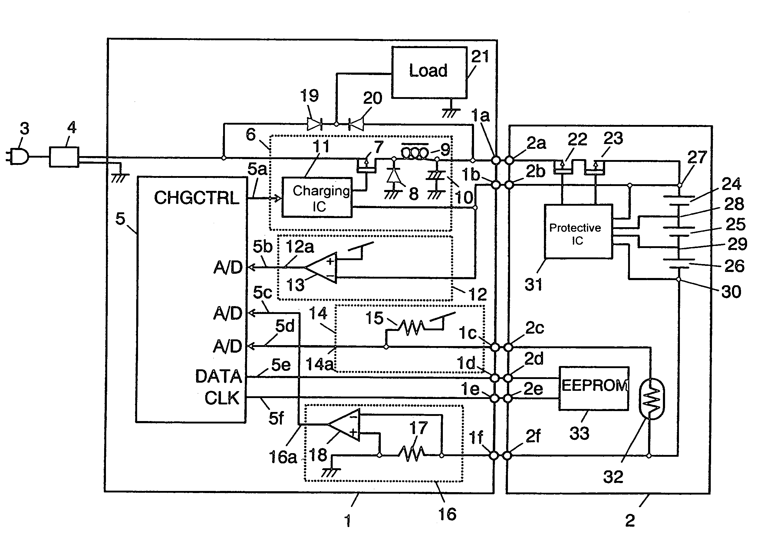
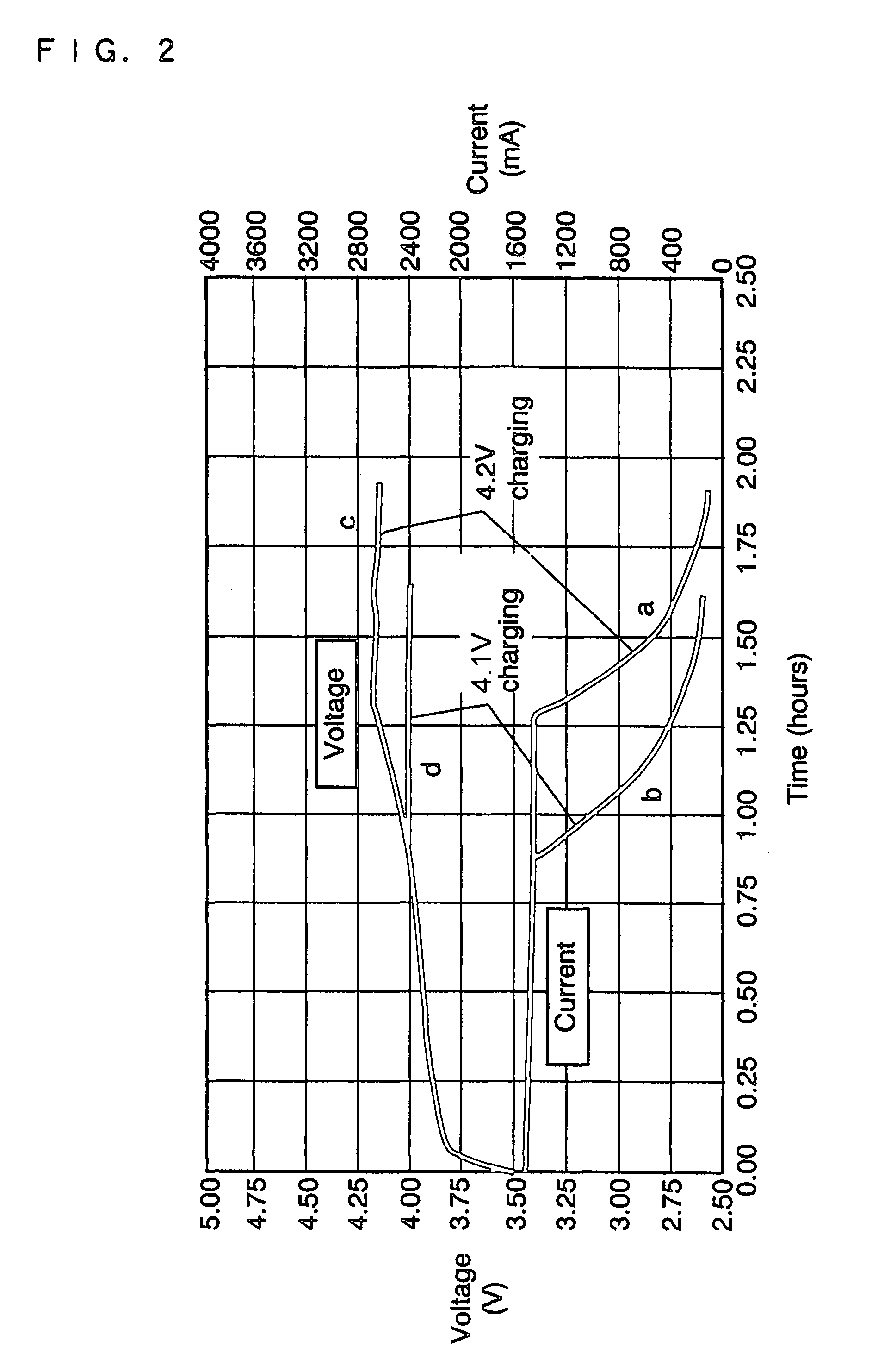
[0028]The charge control device in preferred embodiment 1 of the invention is described below while referring to the accompanying drawings. FIG. 1 is a circuit diagram of the charge control device. FIG. 2 is a charge characteristic diagram of lithium ion secondary battery used in the charge control device. FIG. 3 is a charge and discharge cycle characteristic diagram of battery by difference in charging voltage of lithium ion secondary battery in preferred embodiment 1. FIG. 4 is an explanatory diagram of counting method of charge and discharge cycles of the lithium ion secondary battery.

[0029]The structure shown in FIG. 1 may be roughly divided into main body 1 and battery pack 2 of the charge control device. These two blocks are mutually connected detachably by means of terminals 1a to if at the side of main body 1, and terminals 2a to 2f corresponding to the side of battery pack 2.

[0030]A specified voltage is supplied to main body 1 of the charge control dev...

embodiment 2

Preferred Embodiment 2

[0064]The charge control device in preferred embodiment 2 of the invention is described below while referring to the accompanying drawings. FIG. 5 is a circuit diagram of the charge control device, and FIG. 6 is an explanatory diagram of state of use of rechargeable battery. Preferred embodiment 2 refers also to FIG. 4 showing the charge and discharge cycle counting method of lithium ion secondary battery.

[0065]Due to the characteristics of a lithium ion secondary battery, its deterioration progresses, even if it is not used much. That is, the deterioration characteristics of the lithium secondary battery progress, even if the number of times of charging and discharging is small or kept in charged state. In particular, deterioration is very quick when the battery voltage is maintained in high state. For example, when used in AC floating state by connecting to the AC power supply and using while charging, it is used in a range from point A to point B of battery ...

embodiment 3

Preferred Embodiment 3

[0076]The charge control device in preferred embodiment 3 of the invention is described below while referring to the accompanying drawings. FIG. 7 is a circuit diagram of the charge control device, and FIG. 8 is an explanatory diagram showing an example of setting of voltage value for transfer from CC charging to CV charging corresponding to the duration of its use.

[0077]Due to the characteristics of a lithium ion secondary battery, as mentioned above, its deterioration progresses if not used much. That is, the deterioration characteristics of the lithium secondary battery progresses, even if the number of times of charging and discharging is small or kept in charged state. In consideration of such characteristic of lithium ion secondary battery, in preferred embodiment 3, it is intended to decrease gradually the charging voltage value for transfer from CC charging to CV charging depending on the duration of use from start of secondary battery. Therefore, it is...


PUM

PropertyMeasurementUnit
constant voltageaaaaaaaaaa
specific voltageaaaaaaaaaa
voltageaaaaaaaaaa

Abstract

A charge control device of a secondary battery that allows the use of an electronic apparatus for a long period using a single initial charging, and is capable of extending battery life. The charging device includes a charge circuit for supplying charging current to secondary batteries, a voltage detection circuit for detecting the voltage of secondary batteries, a current detection circuit for detecting the charging current in secondary batteries, a memory such as an EEPROM for recording the number of times of charging or total charge integrated amount in secondary batteries, and a microcontroller for controlling charge circuit, changing over to constant voltage charge after charging secondary batteries 2 at constant current, and decreasing the voltage in constant voltage charging depending on the number of times of charge or total charge integrated amount recorded in the memory of EEPROM.

Description

TECHNICAL FIELD[0001]The present invention relates to a charge control device for charging secondary batteries used in personal computer and other electronic appliances.BACKGROUND ART[0002]Recently, lithium ion secondary batteries were developed as rechargeable secondary batteries, and have been widely used in notebook type personal computers, portable information appliances, digital video camera, digital still camera, mobile telephones and many others.[0003]For charging these lithium ion secondary batteries, various charge control devices have been developed. For example, a device capable of charging plural types of secondary batteries using differing charging methods has been disclosed in Japanese Laid-open Patent Publication No. H11-187587. Japanese Laid-open Patent Publication No. H11-187587 shows a charge control circuit used in both nickel-metal hydride secondary battery and lithium ion secondary battery differing in charging method. In the charging method of lithium ion secon...

Claims


Application Information

Patent Timeline
Patent Type & Authority Patents(United States)
IPC IPC(8): H02J7/04G01R31/36H01M10/44H02J7/00
CPCH02J7/0075H02J7/041H02J7/045H02J2007/0098H02J2007/005H02J7/0069H02J7/0048H02J7/0071H01M10/4257Y02E60/10H02J7/04H02J7/00714H02J7/007182
Inventor WANIBUCHI, TORUTAKAGI, TOSHIYUKI
Owner PANASONIC CORP
Why Eureka
Try Eureka