Method and structure to reset multi-element MTJ

a multi-element, multi-element technology, applied in the field of magnetic field detection, can solve the problems of current reading error, hysteresis of magnetic response, additional cost, etc., and achieve the effect of minimizing non-linearity and hysteresis, widening process margin, and improving production yield

Inactive Publication Date: 2008-07-01
HEADWAY TECH INC
View PDF4 Cites 32 Cited by
  • Summary
  • Abstract
  • Description
  • Claims
  • Application Information

AI Technical Summary

Benefits of technology

[0008]It has been an object of at least one embodiment of the present invention to widen the process margin for the manufacture of devices formed ...

Problems solved by technology

However, a large external magnetic field (one greater than about 60 Oe) could change the single domain state of a GMR or MTJ free layer into multiple domain states, leading to hysteresis of the magnetic response and causing current...

Method used


Image

  • Method and structure to reset multi-element MTJ
  • Method and structure to reset multi-element MTJ
  • Method and structure to reset multi-element MTJ

Examples


Embodiment Construction

[0017]The present invention discloses a structure (and process for its manufacture) that reduces some of the constraints placed on the manufacture and operation of this device, thereby making for a wider processing window which in turn leads to improved process yield. The following references also relate to the field covered by the present invention:

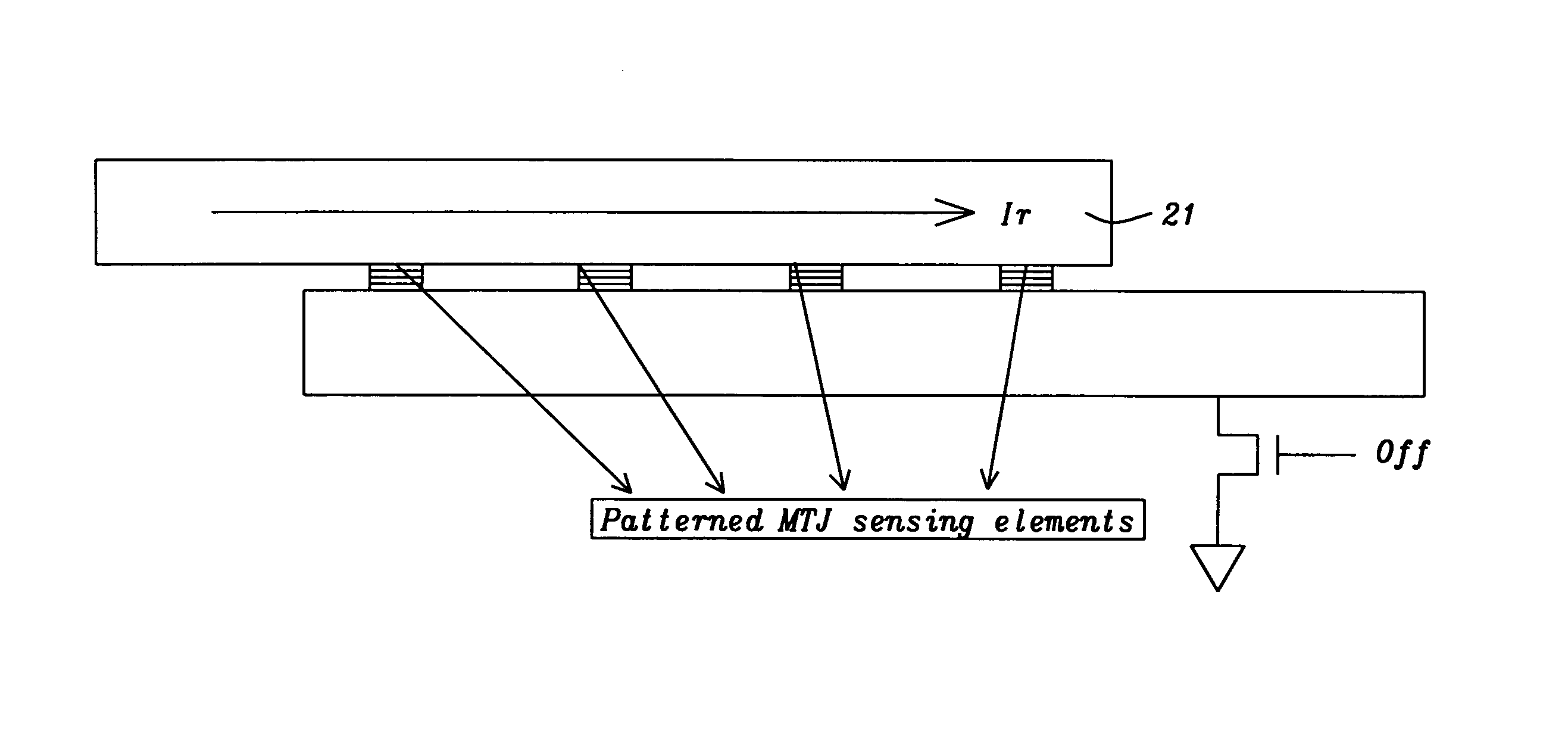
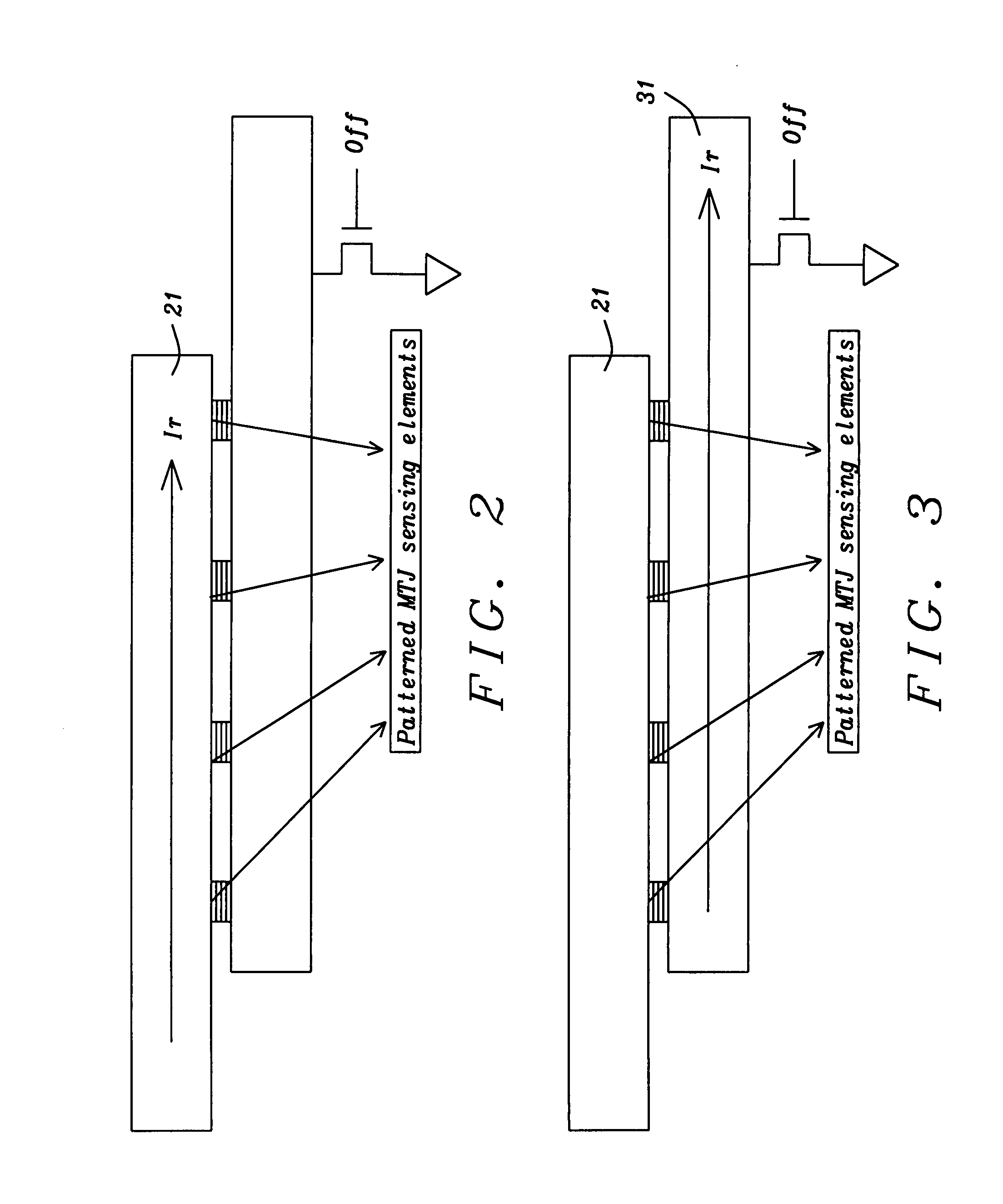
[0018]As noted above, in the present invention multiple ellipse-shaped MTJ elements are arranged along the long axis of a top electrode and a bottom electrode, and MTJ element anisotropies (or their long axis) are also aligned to the long axis of a top electrode and a bottom electrode, the top or bottom electrode serves as a conducting layer carrying a short pulse of electric current flowing along its long axis which is parallel to the total anisotropy (or long axis) directions of the MTJ elements.

[0019]For each MTJ element, when the angle between anisotropy axis and pinned reference magnetization direction is different from 90-degree, a...


PUM


Abstract

The process margin for the manufacture of devices formed from multi-element MTJ or GMR devices has been widened by providing a method and structure to reset the magnetization directions of all pinned layers simultaneously so that their directions of magnetization become evenly distributed. This has the effect of minimizing non-linearity and hysteresis in these devices during their subsequent operation.

Description

[0001]This application is related to HMG06-046, filed on Apr. 23, 2007 as application Ser. No. 11 / 788,912, and herein incorporated, by reference, in its entirety.FIELD OF THE INVENTION[0002]The invention relates to the general field of magnetic field detection by MTJ or GMR devices with particular reference to magnetization reset techniques.BACKGROUND OF THE INVENTION[0003]The present invention relates to a magnetic field sensor using a highly sensitive MTJ (magnetic tunnel junction) device. Its applications include use as a current sensor capable of sensing very small changes in the current flowing through a conductor.[0004]In a conventional current sensor, the sensing elements are two long GMR (Giant Magneto-resistance) bearing stripes disposed adjacent to a conductor to be measured in an in-plane direction. Such a current sensor includes: the conductor bent into a U shape; first and second GMR elements located on the conductor on opposing legs of the U so that a magnetic field ge...

Claims


Application Information

Patent Timeline
IPC IPC(8): G01R33/02
CPCB82Y25/00G01R33/098G01R33/093G01R15/20
Inventor GUO, YIMINGORMAN, GRACE
Owner HEADWAY TECH INC
Why Eureka
Try Eureka