Air separator for low flow rate cooling systems

a cooling system and low flow rate technology, applied in the direction of mechanical equipment, machines/engines, transportation and packaging, etc., can solve the problems of high cost, long time to achieve, and large heat generation of electrical components, so as to facilitate the operation of the cooling system and effectively remove air bubbles. , the effect of low flow ra

Active Publication Date: 2008-07-08
GM GLOBAL TECH OPERATIONS LLC
View PDF10 Cites 39 Cited by
  • Summary
  • Abstract
  • Description
  • Claims
  • Application Information

AI Technical Summary

Benefits of technology

[0006]The present invention is an air separator for low flow rate coolant systems which facilitates operation of the coolant system and effectively removes air bubbles from the liquid coolant thereof, while addressing the major issues associated with such systems.
[0010]The air separator provides both time and space for air separation from the coolant to occur. Proper integration of the air separator with the coolant path of the low flow rate cooling circuit eliminates the need for additional system hardware, such as for example vent valves, and simplifies the service fill procedure.
[0013]Flowbench development has shown that an air separator is highly effective in removing air bubbles from the coolant circuit, thereby maximizing heat transfer within the system.
[0015]Accordingly, it is an object of the present invention to provide an air separator for low flow rate coolant systems which facilitates operation of the coolant system and effectively removes air bubbles from the coolant, while addressing the major issues associated with such systems.

Problems solved by technology

Problematically, these electrical components generate heat which must be dissipated in order to operate within predetermined parameters.
While low flow rate coolant systems perform well, there are a number of operational issues that need careful attention.
A first issue relates to separation and removal of air bubbles from the coolant after a service fill, which is difficult because of the low coolant flow velocities.
Air bubbles removal may require complex steps using vent valves in the system, may take a long time to accomplish, that is, require several system cycles, or may not be possible in some cases.
Another issue relates to the fact that low flow rate cooling systems only use electric coolant pumps, wherein the coolant pressure drop at each component must be minimized to keep the size and power consumption of the electric coolant pump as small as possible.
Yet another issue is that as the motor vehicle is driven, the vehicle motion in the vertical, fore-aft, and side-to-side directions can create churning of the coolant contained within the coolant reservoir of the system.
This coolant churning in a flow-through coolant reservoir of a low flow rate cooling system can result in the creation of air bubbles which introduces air into the coolant.
Yet another issue of low flow rate cooling systems is that air bubbles in the coolant create a thermal barrier to heat transfer between the electronic component and the coolant and between the coolant and the heat rejecting heat exchanger.
Another issue is that multi-path low flow rate cooling systems require a central return path.
Yet another issue is that low flow rate coolant pumps can easily loose prime with the introduction of small amounts of air which can render the cooling system inoperative causing thermal stress or failures of the components that are to be cooled by the system.

Method used


Image

  • Air separator for low flow rate cooling systems
  • Air separator for low flow rate cooling systems
  • Air separator for low flow rate cooling systems

Examples


Embodiment Construction

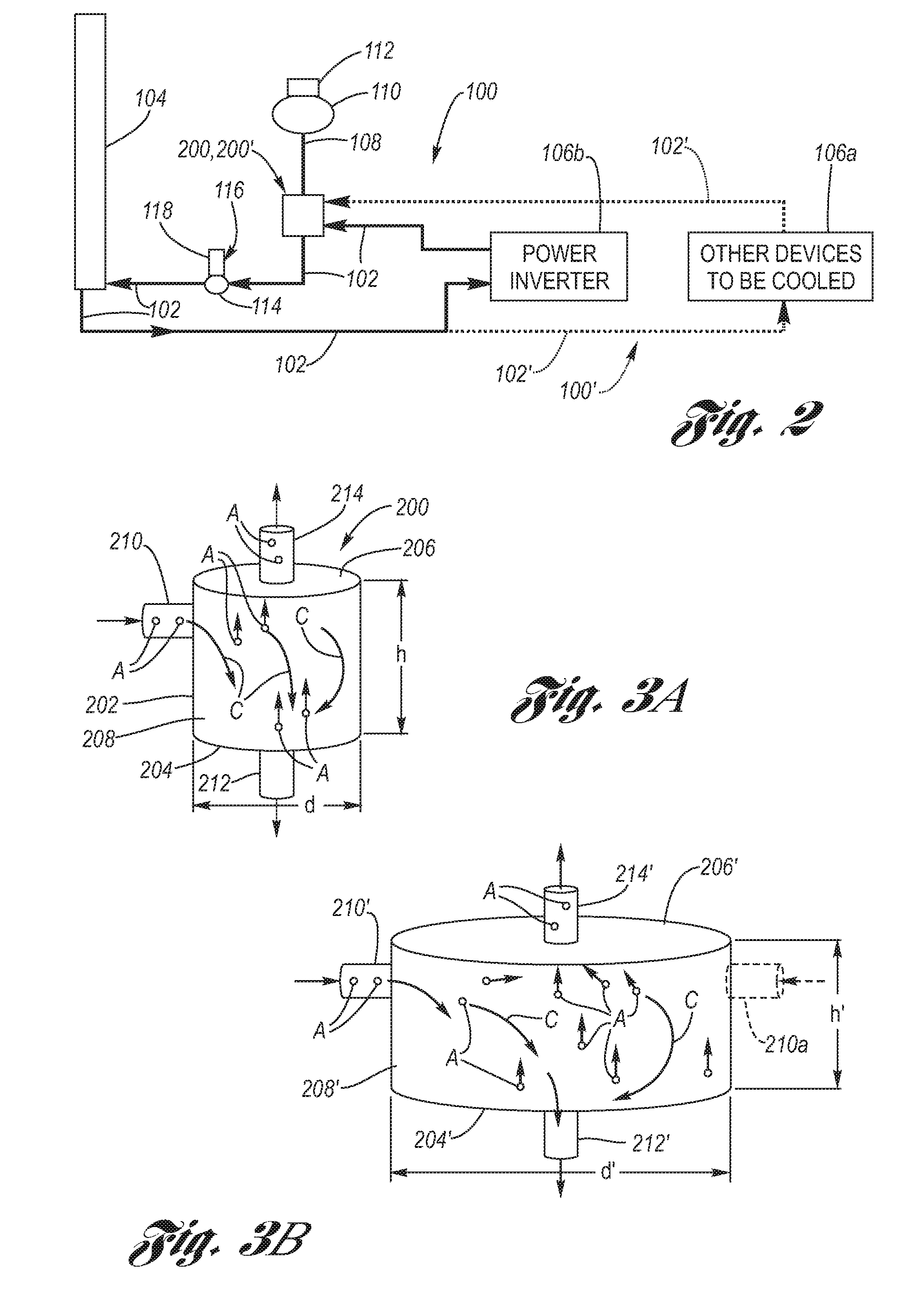
[0023]Referring now to the Drawing, FIGS. 2 through 4 depict various structural and functional aspects of a low flow rate coolant system, suitable for a motor vehicle, which incorporates an air separator according to the present invention.

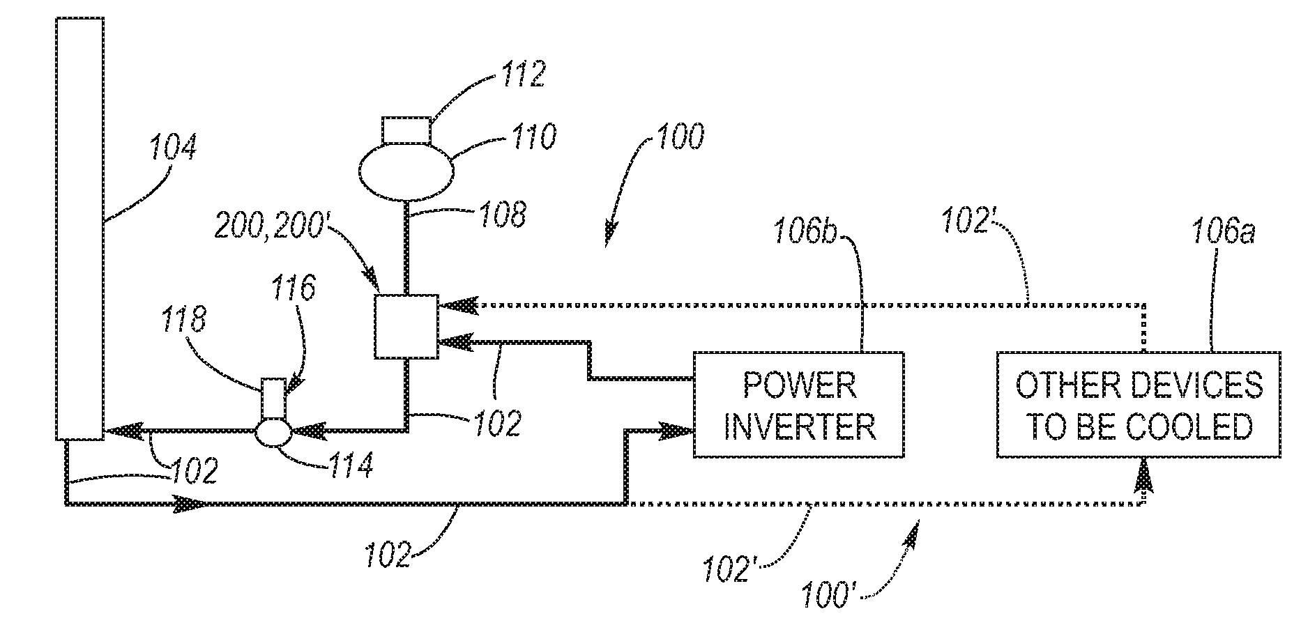
[0024]Turning attention firstly to FIG. 2, a low flow rate cooling system 100 includes coolant piping 102, 102′ by which a liquid coolant C (see FIGS. 3A and 3B) flows through a main heat exchanger 104, whereat heat of the coolant is exchanged with the atmosphere, and flows by piping 102 to various electronic devices 106a, which may be connected in series, parallel or series-parallel with respect to each other, or to other electronic devices 106b via piping 102′ of one or more second low flow rate coolant loops 100′. At the electronic devices 106a, 106b heat generated thereby is removed by absorption by the coolant flowing therepast. The coolant flows through an air separator 200, 200′ according to the present invention, which has a coolant reservo...


PUM


Abstract

An air separator for low flow rate coolant systems which removes air from the liquid coolant thereof. The air separator is a closed canister having a bottom wall, a top wall at a gravitationally high location with respect to the bottom wall, and a sidewall sealingly therebetween. A coolant inlet is at the sidewall, a pump outlet is at the bottom wall and a coolant reservoir outlet is at the top wall. The coolant reservoir outlet is connected to a coolant reservoir gravitationally elevated with respect to the canister. A much larger cross-sectional area per unit length of the canister relative to the piping results in a coolant dwell time in the canister that encourages coolant air bubbles to migrate toward the coolant reservoir.

Description

TECHNICAL FIELD[0001]The present invention relates to low flow rate cooling systems of the type used in the motor vehicle art to cool electronics, as for example those associated with hybrid and fuel cell motor vehicles. Still more particularly, the present invention relates to an air separator of the low flow rate cooling system for removing air bubbles from the coolant liquid thereof.BACKGROUND OF THE INVENTION[0002]As for example shown at FIG. 1, a low flow rate cooling system 10 includes coolant piping 12 whereby a liquid coolant flows through a main heat exchanger 14 whereat heat of the coolant is exchanged with the atmosphere, and whereby heat is absorbed from various electronic devices 16a, 16b which may be connected in series, parallel or series-parallel with respect to each other. The coolant flows through a coolant reservoir (or surge tank) 18 having a removable cap 20 whereat filling is performed and air can escape. A pump 22 powered by an electric motor 24 (in combinatio...

Claims


Application Information

Patent Timeline
Patent Type & Authority Patents(United States)
IPC IPC(8): F01P9/00
CPCF01P11/04F01P11/028F01P5/12
Inventor CLAYPOLE, GEORGE M.NEMESH, MARK D.ZIEHR, LAWRENCE P.LOMBARDO, PAUL S.
Owner GM GLOBAL TECH OPERATIONS LLC
Why Eureka
Try Eureka