Ultraclean magnetic mixer

a magnetic mixer and ultra-clean technology, applied in mechanical equipment, transportation and packaging, sliding contact bearings, etc., can solve the problems of product spoilage, difficult cleaning of areas within the mixer, and contamination of the cleaning of the mixing vessel and other equipment, so as to eliminate the contamination of the liquid and eliminate the wear of the thrust bearing

Active Publication Date: 2008-07-08
ALFA LAVAL CORP AB
View PDF18 Cites 24 Cited by
  • Summary
  • Abstract
  • Description
  • Claims
  • Application Information

AI Technical Summary

Benefits of technology

[0010]Another object of this invention is to provide a magnetically-coupled liquid mixer which eliminates contamination of the liquid.
[0011]Another object of this invention is to provide a magnetically-coupled liquid mixer which eliminates wear of the thrust bearing when the thrust bearing is not submerged in the liquid being mixed.
[0013]Another object of this invention is to provide a magnetically-coupled liquid mixer which enables the mixer to be fully cleaned while being operated in the mixing vessel in which the mixer is mounted.
[0015]Still another object of this invention is to provide a magnetically-coupled liquid mixer which can withstand the high temperature conditions of the cleaning cycles required for the mixer.
[0017]The instant invention overcomes the above-noted problems and shortcomings and satisfies the objects of the invention. The invention is an improved magnetically-coupled mixer for liquids Of particular note is that the instant invention provides a mixer which practically eliminates bearing wear and therefore contamination of the liquid being mixed while providing good bearing support for the rotatably-driven portion of the mixer when the driven portion experiences the fluid dynamic forces caused by mixing viscous liquids at higher rates of rotation.
[0019]In highly preferred embodiments of the inventive mixer, the first and second magnet arrays are positioned with respect to one another such that the first and second thrust bearing surfaces contact one another in the presence of above-threshold fluid dynamic thrust forces on the driven portion. Under such forces, i.e., when the fluid-dynamic forces on the driven portion are greater than the magnetic force parallel to the axis of the stub shaft, contact between the first and second thrust bearing surfaces provides stable support for the driven portion experiencing a variety of forces from both the magnetically-coupled driving forces and the fluid dynamic forces from the liquid being mixed.

Problems solved by technology

One source of contamination comes from seals which may be required to seal a piece of equipment which must penetrate into the mixing vessel.
Another source of contamination is the relative movement of bearing surfaces against one another.
The cleaning of the mixing vessel and other equipment is also a source of contamination.
Product which may spoil can become trapped in areas which are hard to reach during the cleaning process.
Current magnetically-coupled mixers, while eliminating the penetration of the mixing vessel from a drive shaft, still produce contamination caused by dry bearing contact, and because of such bearing contact, also contain areas within the mixer which are difficult to clean.
Under such conditions, the fluid dynamic forces on the mixing element can be both large and rapidly changing due to such variables as high liquid viscosity, high mixing rates, and turbulence.

Method used


Image

  • Ultraclean magnetic mixer
  • Ultraclean magnetic mixer
  • Ultraclean magnetic mixer

Examples


Embodiment Construction

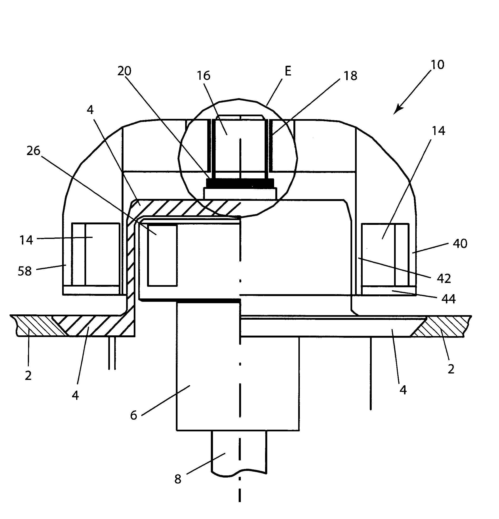
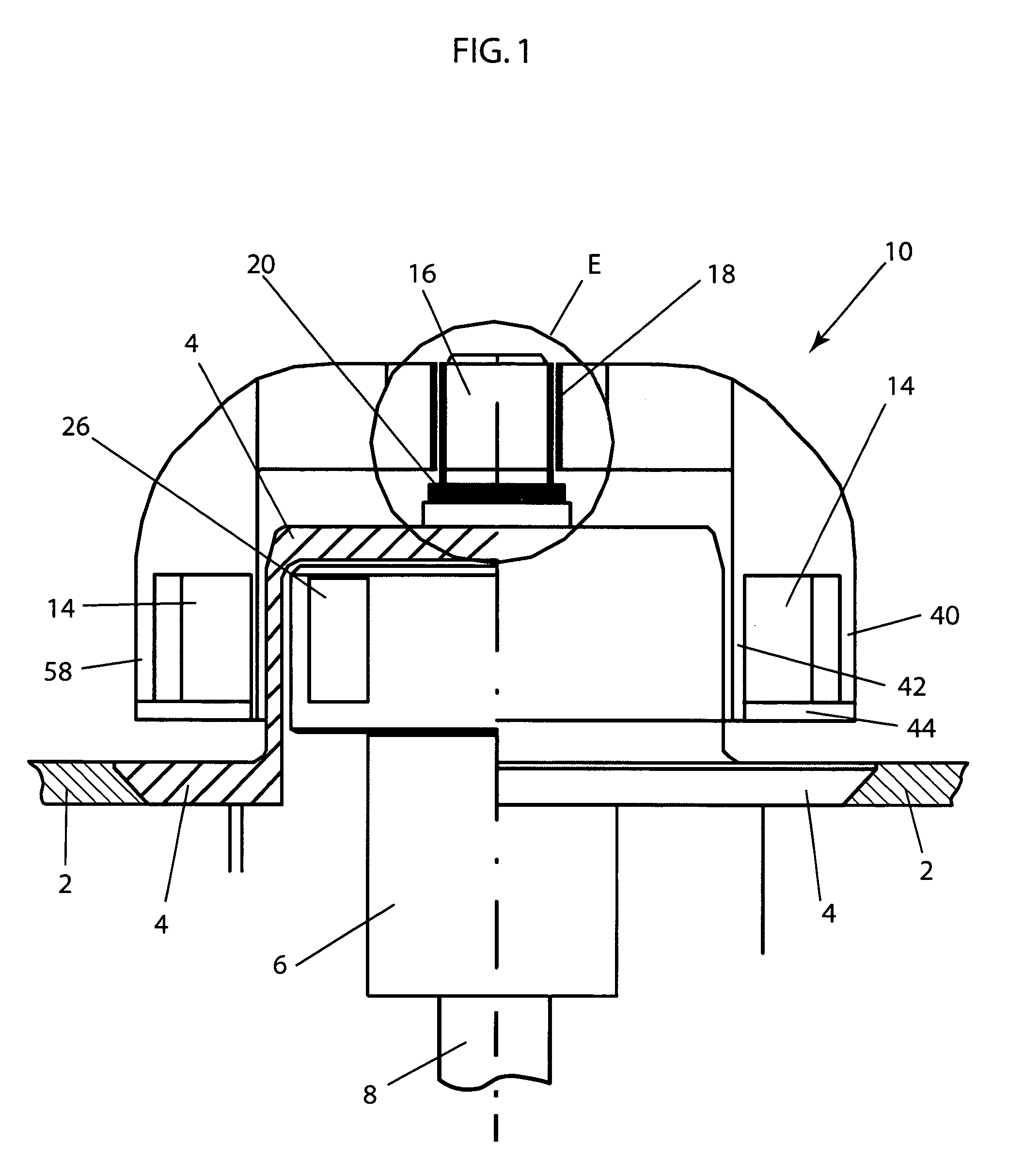
[0037]FIG. 1 shows one embodiment of a magnetically-coupled liquid mixer 10. In FIGS. 1-6, magnetically-coupled liquid mixer 10 and its various elements are largely shown in highly schematic fashion. In FIG. 1, for example, certain elements such as the rotary power source for driving mixer 10 through a drive shaft 8 and the mixing elements (e.g., blades) attached to a driven portion 12 of mixer 10 have been left out of the figure to simplify the description of the present invention. Both the rotary power source and the form of the mixing elements can vary significantly. For example, the rotary power source may be an electric motor, a pneumatic motor, a hydraulic motor, or any other appropriate source of rotary power. The mixing elements may be, for example, impeller blades of the form illustrated in FIGS. 4A-4D or any other appropriate elements such those with sharp edges for shearing the fluid being mixed.

[0038]Referring again to FIG. 1, mixer 10 is mounted to a mixing vessel 2 thr...


PUM


Abstract

In a magnetically-coupled liquid mixer of the type having a drive mount secured to and extending into a mixing vessel, an external first magnet array adjacent to the drive mount, a stub shaft extending from the drive mount into the vessel and having a first thrust bearing surface, and a driven portion rotatably-mounted on the stub shaft and having a second thrust bearing surface and a second magnet array, the improvement wherein the first and second arrays are positioned with respect to one another such that the first and second thrust bearing surfaces are spaced apart at least in the absence of above-threshold fluid dynamic thrust forces on the driven portion.

Description

FIELD OF THE INVENTION[0001]This invention relates generally to mixing technology such as is required for the mixing of food products, pharmaceuticals, and chemical products. More particularly, it relates to mixers which are magnetically coupled through the wall of a mixing vessel so that no seal is required in the vessel wall in order to transmit power to the mixer.BACKGROUND OF THE INVENTION[0002]Many production processes require mixing of liquids in an ultraclean operation. Such production processes may include the mixing of products such as pharmaceuticals, foods and chemicals. Certain of these may require aseptic processing. The term ultraclean as used herein refers in general to particularly stringent requirements for the levels of contamination which are acceptable in such processes.[0003]Contamination in mixing processes may come from a number of sources. Among these are the mixing equipment itself and the cleaning processes which are invariably required during the use of su...

Claims


Application Information

Patent Timeline
Patent Type & Authority Patents(United States)
IPC IPC(8): B01F13/08
CPCB01F13/0827B01F15/00071B01F2215/0032F16C39/063F16C32/0417F16C17/02B01F33/4534B01F35/146B01F2101/22B01F33/45B01F33/453
Inventor ANDERSSON, PER-OLOF K.
Owner ALFA LAVAL CORP AB
Why Eureka
Try Eureka