
Substrate processing apparatus and substrate processing method

Inactive Publication Date: 2008-07-08
DAINIPPON SCREEN MTG CO LTD
View PDF18 Cites 18 Cited by
  • Summary
  • Abstract
  • Description
  • Claims
  • Application Information

AI Technical Summary

Benefits of technology

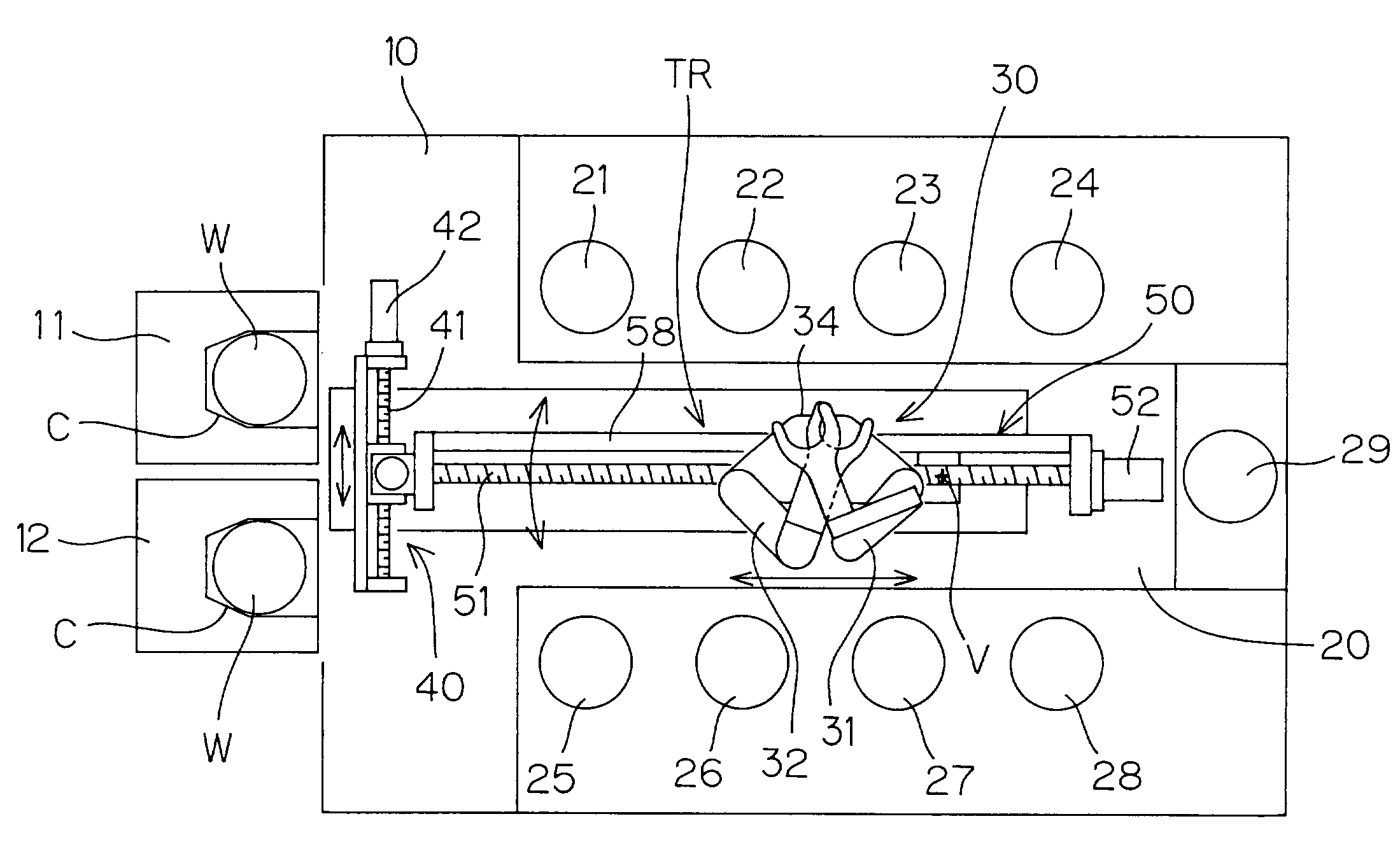
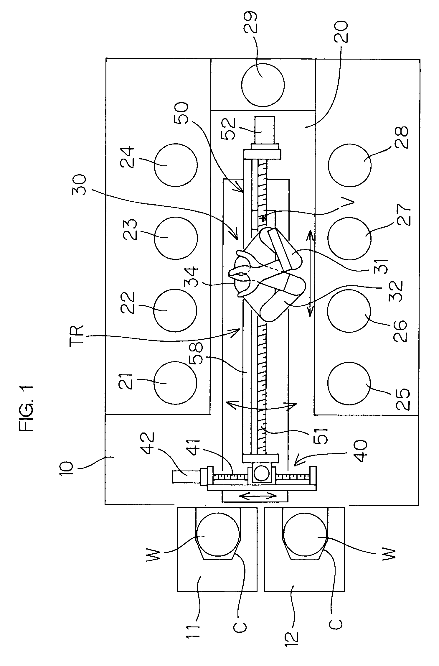
[0014]It is an object of the present invention to provide a substrate processing apparatus having units arranged along two straight lines crossing each other, the substrate processing apparatus being simplified in arrangement, thus reducing the production cost thereof.
[0015]It is another object of the present invention to provide a substrate processing apparatus which eliminates the transfer of a substrate between two transfer robots, thus not only simplifying the operation of a single transfer robot, but also reducing the chances of the substrate being contaminated.
[0016]It is a further object of the present invention to provide a substrate processing method which eliminates the transfer of a substrate between two transfer robots, thus not only simplifying the operation of a single transfer robot, but also reducing the chances of the substrate being contaminated.

Problems solved by technology

This makes the apparatus complicated in arrangement, thus accordingly increasing the production cost thereof.
Further if one of the two transfer robots gets out of order, any substrate cannot be processed.
This is disadvantageous also in reliability.
This results in a variety of problems as follows.
It becomes however complicated to program such that the two robots are operated in good timing.
This accordingly increases the chances of particles occurring and attaching to the substrate.
Thus, the substrate is disadvantageously easily contaminated.
This disadvantageously generates particles to contaminate the substrate.

Method used


Image

  • Substrate processing apparatus and substrate processing method
  • Substrate processing apparatus and substrate processing method
  • Substrate processing apparatus and substrate processing method

Examples


second embodiment

[0068]FIG. 3A is a plan view illustrating the arrangement of a transfer robot TR1 to be used in a substrate processing apparatus according to the present invention, and FIG. 3B is a side view of FIG. 3A. Instead of the transfer robot TR, the transfer robot TR1 can be used in the substrate processing apparatus shown in FIG. 1.

first embodiment

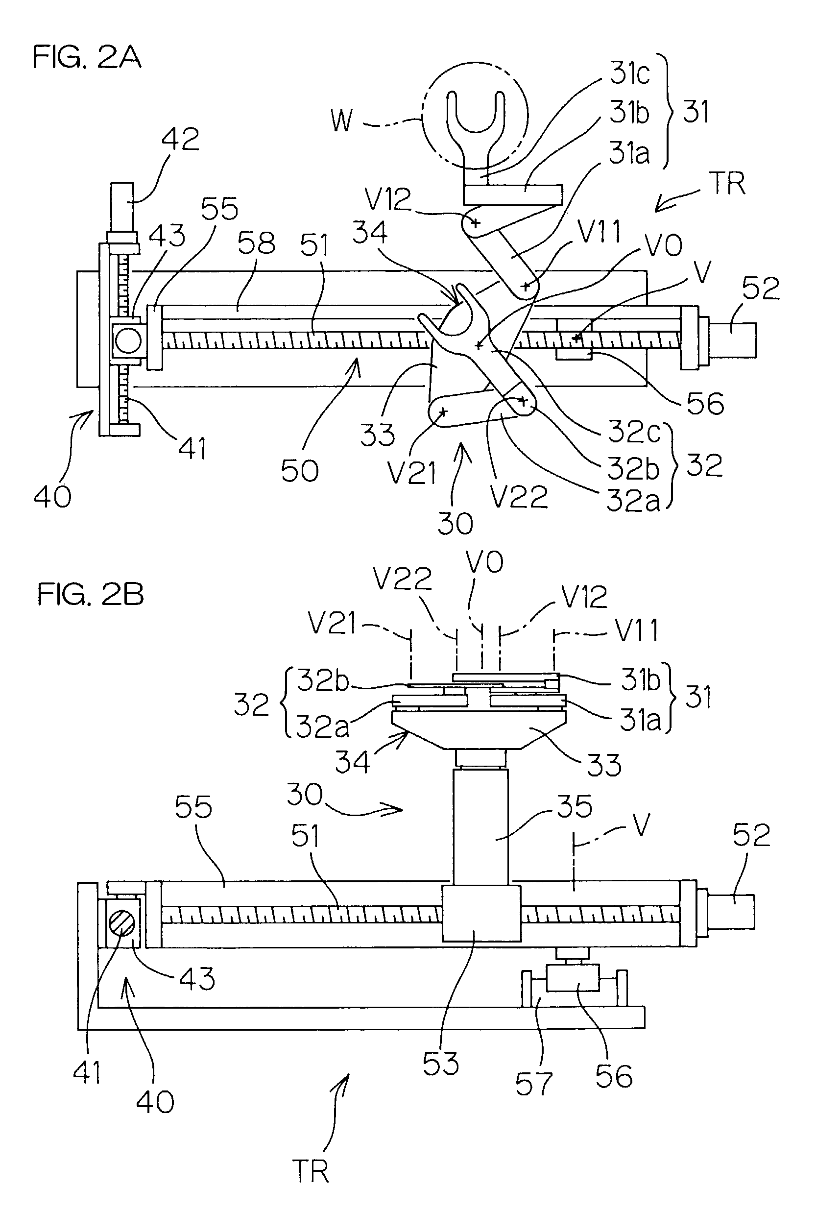
[0069]The transfer robot TR1 has a ball screw mechanism 60 comprising a screw shaft 61 disposed along the second transfer passage 20 (See FIG. 1). This ball screw mechanism 60 comprises the screw shaft 61, a carriage 62 having a ball nut threadedly connected to the screw shaft 61, and a motor 63 for rotationally driving the screw shaft 61. Rails 64, 65 are parallel to the screw shaft 61 for guiding the movement of the carriage 62. Unlike the rail 58 in the first embodiment above-mentioned, the rails 64, 65 are not swung but are fixed as extending in the direction along the second transfer passage 20.

[0070]A robot main body 70 is fixed onto the carriage 62. More specifically, the robot main body 70 comprises a base stand 71 fixed onto the carriage 62, a vertical multiarticular arm 72 attached to the base stand 71, a rotationally driving mechanism 73 attached to the vertical multiarticular arm 72, and a substrate holding unit 74 to be driven, rotatably around a perpendicular axis of r...


PUM


Abstract

A substrate processing apparatus for processing a substrate while transferring the substrate among a plurality of units with which the substrate is to be processed or on which the substrate is to be placed. This apparatus is provided with: a first unit group disposed along a linear first line; a second unit group disposed along a linear second line crossing the first line at a predetermined angle; and a transfer robot capable of transferring and receiving a substrate to and from the first unit group and the second unit group.

Description

BACKGROUND OF THE INVENTION[0001]1. Field of the Invention[0002]The present invention relates to a substrate processing apparatus for and a substrate processing method of executing processings on any of a variety of substrates such as a semiconductor wafer, a liquid-crystal-display-device glass substrate, a plasma-display glass substrate, an optical-disk substrate, a magnetic-disk substrate, a photomagnetic-disk substrate, a photomask substrate and the like.[0003]2. Description of Related Art[0004]In production of a semiconductor device or a liquid crystal display device, there is used a substrate processing apparatus for executing, on a substrate (semiconductor wafer or glass substrate), a variety of processings such as a plating processing, a resist coating processing, a cleaning processing and the like.[0005]Such a substrate processing apparatus is formed for example by an indexer section in which a substrate is carried in / out from a cassette capable of housing a plurality of sub...

Claims


Application Information

Patent Timeline
IPC IPC(8): H01L21/677B25J9/02B25J9/06B25J9/04B65G49/07
CPCB25J9/023H01L21/67766H01L21/67742B25J9/042Y10S414/141Y10S414/137
Inventor KOYAMA, YOSHIHIROMIZOHATA, YASUHIRO
Owner DAINIPPON SCREEN MTG CO LTD
Learn More