Spiral wound membrane element and a process for preventing telescoping of the filter element

a filter element and spiral wound technology, applied in gravity filters, cartridge filters, water/sludge/sewage treatment, etc., can solve the problems of significant reduction of the limited efficiency of the filter elemen

Inactive Publication Date: 2008-07-08
ENVIRO HLDG
View PDF11 Cites 12 Cited by
  • Summary
  • Abstract
  • Description
  • Claims
  • Application Information

AI Technical Summary

Benefits of technology

[0019]The present inventors has realized that the filtration using a spiral wound ultra filter can be improved by a process for ultrafiltration using one or more spiral would membrane filter elements arranged in a cylindrical pressure vessel, where each filter sections comprises one or more membranes, each consisting of a central permeate spacer covered on both sides by the separating membrane, connected at one edge with a permeate pipe and blocked at the three other edges, wound around the central permeate pipe with a concentrate spacer so the membranes and the concentrate spacers are lying alternating in the wound element and allowing the fluid from the space between the filter element and the pressure vessel entering into the concentrate spacer in a tangential spiralling direction, where in a cross section at any location along the filter element the pressure in the space between the spiral wound membrane filter sections and the cylindrical pressure vessel is higher than or equal to the pressure in the concentrate spacers between two membranes.
[0022]This enables the filter elements to be operated at pressures significantly higher that the pressures used in the prior art, such as a difference of 2 bar of more between the entrance and the outlet of a filter element having a length of approximately 1 m. Such a high pressure difference provides for a higher efficiency of the filtration element, which again secures that a higher concentrating per area of separating membrane may be achieved using this process and. Further a lower energy consumption compared with processes according to the prior art may be achieved.
[0025]In a preferred embodiment this ATD is provided with a flow restrictor that secures that the incoming fluid in the following filter element meets the end of the filter element at a lower pressure than said fluid meets the periphery of said filter element.

Problems solved by technology

In the locations where the pressure is higher inside the filter element than in the space between the filter element and the vessel there is a tendency of the spiral wound element to unwind or to telescope with the result that channels are formed inside the filter element, which significantly reduces the efficiency of the filter element.
In practice it is experienced that the tendency to unwinding or telescoping increases with higher pressure gradients and flow velocity of the liquid with the consequence that the unwinding or telescoping effect limits the pressure gradient that can be applied to a spiral wound element, and because the pressure difference is the driving force in the filtration operation the efficiency of said filter element is limited.

Method used


Image

  • Spiral wound membrane element and a process for preventing telescoping of the filter element
  • Spiral wound membrane element and a process for preventing telescoping of the filter element
  • Spiral wound membrane element and a process for preventing telescoping of the filter element

Examples


examples

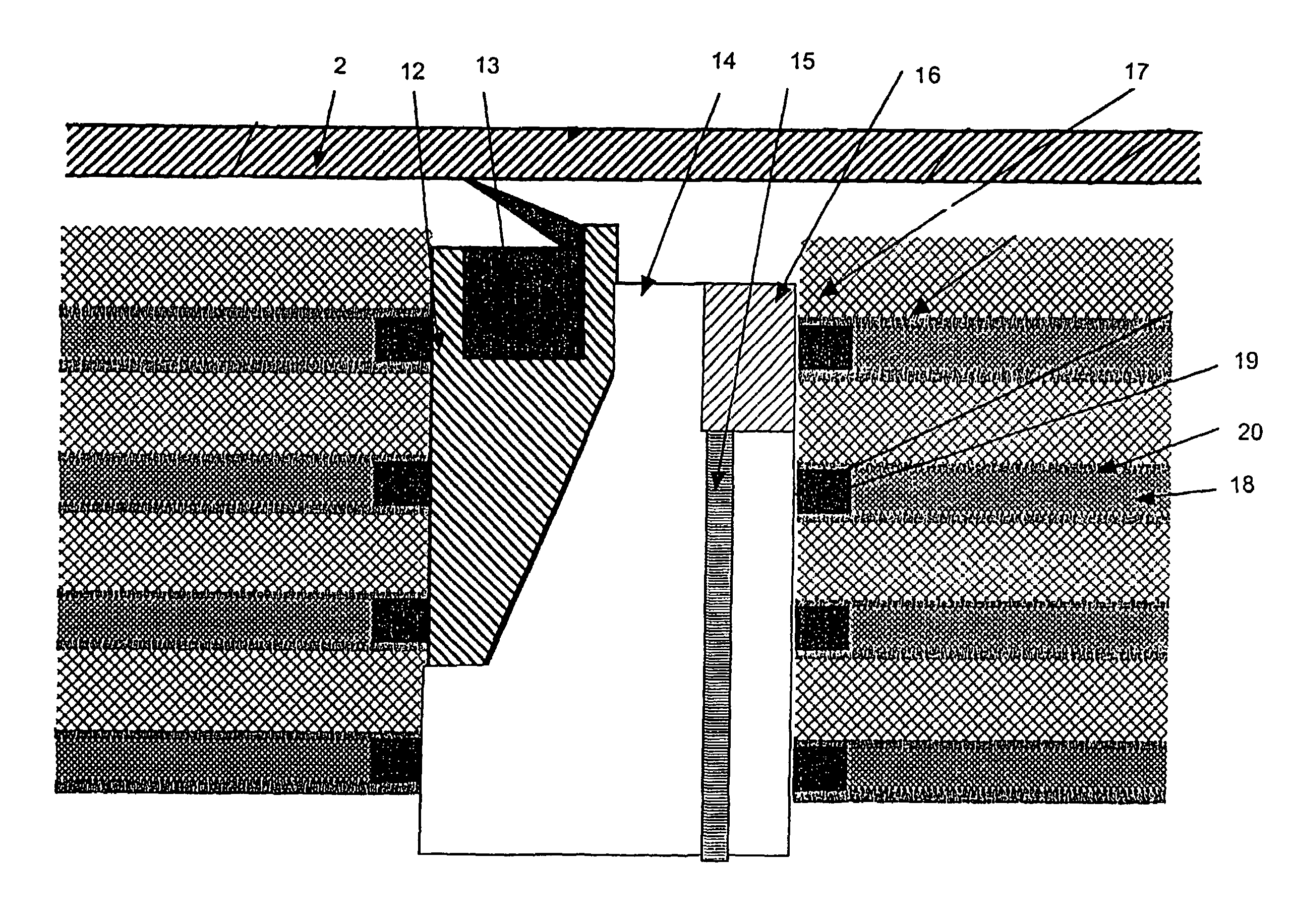
[0085]An arrangement according to FIG. 12 was used for filtrations, where the dimensions and streams were as indicated in the table below. The terms in the table are as indicated in FIG. 12.

[0086]

ex 1ex 2ex 3ex 4r0mm14141414r1mm18181818r2mm55453526.5r3mm75757779Rmm80808080r4mm1008582.581.5g1mm1619137g2mm1211.562.4hmm35.531.2r4-Rmm2052.51.5A(r1, r2)mm28485534428301188A(r2, g1)mm25529537228591165A(r3, g2)mm25655541929031191A(r3, h)mm2141425921451596A(r4, R)mm21005325131257754A(r3, r4)mm213744502627561261Qfeedm3 / h25251717axial / radial0.500.500.500.50flowradial flowm3 / h12.512.58.58.5QrAxial flowm3 / h12.512.58.58.5Qav(r1, r2)m / s0.821.301.673.97v(r2, g1)m / s1.261.291.654.05v(r3, g2)m / s1.231.281.633.96v(r3, r4)m / s0.511.381.713.75v(r3, h)m / s2.461.341.633.96v(r4, R)m / s0.961.341.853.10

[0087]In the table the expression A(r1,r2) is intended to mean the area between the r1 and r2. Similar the expression v(r1,r2) is intended to mean the velocity of the stream passing between r1 and r2. Other express...


PUM

PropertyMeasurementUnit
lengthaaaaaaaaaa
diameteraaaaaaaaaa
diameteraaaaaaaaaa

Abstract

A process for ultrafiltration using a spiral wound membrane filter is disclosed where the pressure in the space between the filter element and the pressure vessel is higher than or equal to the pressure inside the filter element. Using these conditions the static force created by the pressure provides a high friction between different sheets in the spiral wound filter element, which efficient prevents unwinding or telescoping of the filter element. Using this configuration it is possible to perform the ultrafiltration using a higher differential pressure across the filter element than would otherwise have been possible which leads to a higher efficiency and a low energy consumption. Further an anti telescoping device (ATD) and a spiral wound filter element, which are particular suited for the disclosed process, are described.

Description

[0001]The invention relates to an improved method for ultra filtration, an anti telescoping device (ATD) particular suited for use in said method and an ultra filter particular suited for use in said method.BACKGROUND FOR THE INVENTION[0002]The use of ultra filtration to concentrate a feed stream by passing smaller molecules through the filter, while retaining larger molecules are well known in the industry. Uses of ultrafilters are in particular widespread within the dairy industry and in the pharmaceutical industry. Another well-known use is known as reverse osmosis where essentially all molecules larger that water is retained and the permeate is pure water. Reverse osmosis is used e.g. for desalting seawater in order to produce sweet water for household use or irrigation.[0003]The basis for all these uses is membranes having suitable permeability properties for the intended use. As the throughput obviously is dependent on the surface area of the membrane it is desirable to use la...

Claims


Application Information

Patent Timeline
Patent Type & Authority Patents(United States)
IPC IPC(8): B01D63/10B01D61/18B01D63/12C12M1/12B01D61/14B01D61/20
CPCB01D61/20B01D63/10B01D63/12B01D63/106B01D2313/12B01D61/18B01D63/107B01D63/101
Inventor MOLLER, JENS KLOPPENBORG
Owner ENVIRO HLDG
Why Eureka
Try Eureka