

Tandem rotary electric machine
a technology rotary electric motor, which is applied in the direction of magnetic circuit rotating parts, magnetic circuit shape/form/construction, windings, etc., can solve the problems of reducing the degree of adaptation of tandem rotary electric machine to various applications, reducing the mounting space of a vehicle, etc., to reduce the entire size and weight of the rotary electric machine, simplifying the entire configuration of the tandem rotary electric machine, and reducing friction loss
- Summary
- Abstract
- Description
- Claims
- Application Information
AI Technical Summary
Benefits of technology
Problems solved by technology
Method used
Image

Examples
first embodiment
(Entire Configuration)
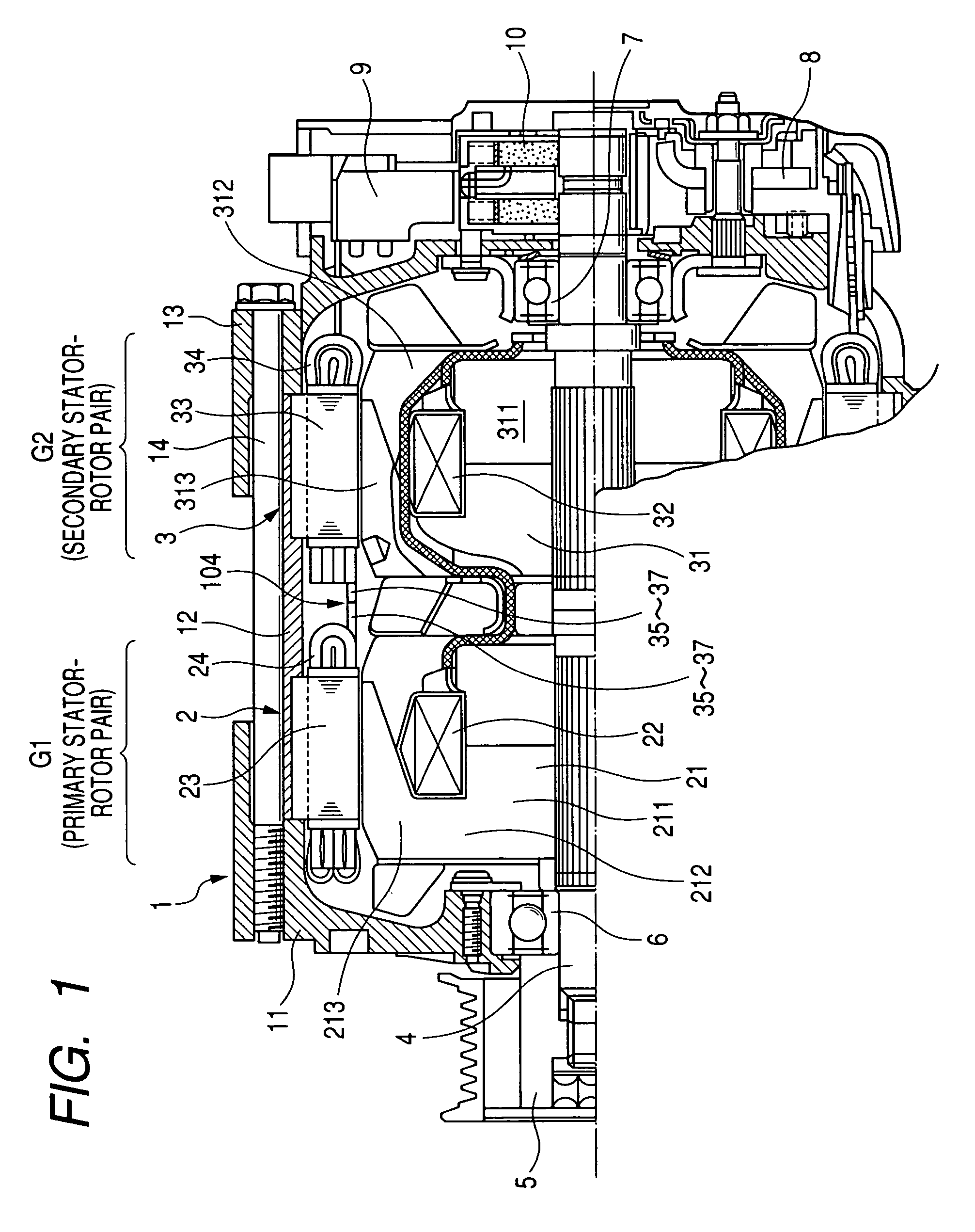
[0045]The entire configuration of a tandem electric rotary machine for vehicle (or a vehicle alternator) according to the first embodiment of the present invention will now be described with reference to FIG. 1.
[0046]FIG. 1 is a sectional view along a rotor shaft direction of the tandem electric rotary machine having dual stator-rotor pairs, a primary rotary electric machine section 2 (also referred to as G1 in the diagrams) and a secondary rotary electric machine section 3 (or referred to as G2 in the diagrams), arranged in a tandem mechanism according to the first embodiment. The tandem electric rotary machine has a housing 1, the primary rotary electric machine section 2 (G1), the secondary rotary electric machine section 3 (G2), a rotor shaft 4, a pulley 5, bearings 6 and 7, a rectifier 8, a regulator 9, and a slip ring power supply device 10.
[0047]As shown in FIG. 1, the housing 1 comprises a front housing 11, a center housing 12, and a rear housing 13. Th...
second embodiment
[0080]A description will now be given of the configuration of the tandem rotary electric machine according to the second embodiment of the present invention with reference to FIG. 3.
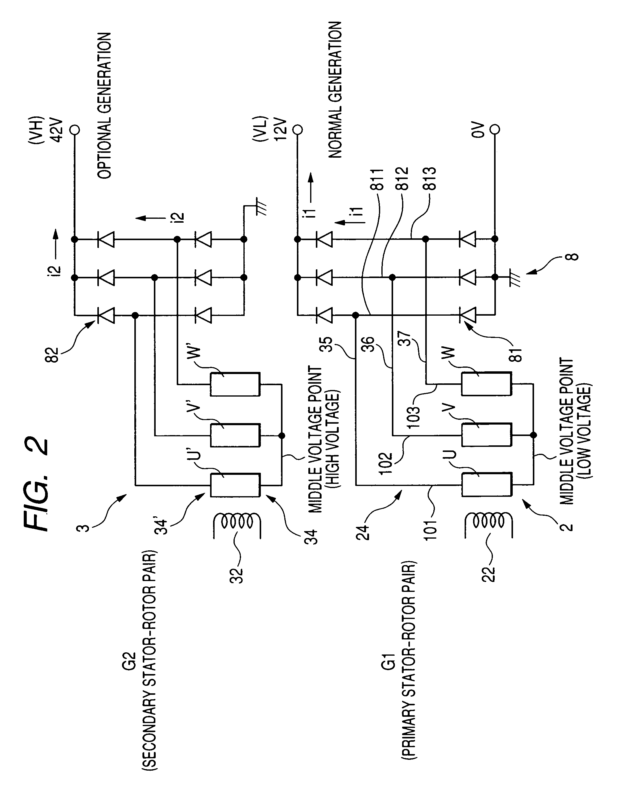
[0081]In the second embodiment, a DC high voltage output terminal of the three phase full wave rectifier 81 for the primary rotary electric machine section 2 (G1) is connected to the DC low voltage output terminal of the three phase full wave rectifier 82 for the secondary rotary electric machine section 3 (G2) through a connection node A.
[0082]It is possible to adjust the output voltage (12 Volts) and output current from the three phase full wave rectifier 81 by adjusting the magnitude of the exciting current If1 to be flowing into the field coil 22. Similarly, it is possible to adjust the output voltage (42 Volts) and output current from the three phase full wave rectifier 82 by adjusting the magnitude of the exciting current If2 to be flowing into the field coil 32. Thus, through the connection node A...
third embodiment
[0083]A description will now be given of the configuration of the tandem rotary electric machine according to the third embodiment of the present invention with reference to FIG. 4.
[0084]As shown in FIG. 4, the slip ring power supply device 10 has a pair of brush 200 and a slip ring 201 contacted to the brush 200, and a pair of brush 202 and a slip ring 203 contacted to the brush 202. Reference number 204 designates a transistor for controlling ON / OFF operation of the exciting current flowing through the field coil 22. Reference number 205 denotes a transistor for controlling ON / OFF operation of the exciting current flowing through the field coil 32. Reference number 206 indicates an emitter follower transistor for amplifying the base current of the transistor 204, 207 designates an emitter follower transistor for amplifying the base current of the transistor 205, and reference character D indicates fly wheel diodes. Those electric components such as the transistors 204, 205, 206, a...
PUM
 Abstract
Description
Claims
Application Information