Whiteboard view camera

a whiteboard and view camera technology, applied in the field of whiteboard capture camera design, can solve the problems of affecting the active participation and involvement of many participants, affecting the effect of many participants, and dramatically varying the resolution of whiteboard portions, etc., and achieves the effect of small aperture, no image noise, and large apertur

Inactive Publication Date: 2008-07-08
MICROSOFT TECH LICENSING LLC
View PDF70 Cites 17 Cited by
  • Summary
  • Abstract
  • Description
  • Claims
  • Application Information

AI Technical Summary

Benefits of technology

[0016]The whiteboard view camera differs from an ordinary camera by allowing the lens to tilt with respect to the sensor plane, and shift with respect to the central ray. When the tilt angle α is zero, then the resolution of whiteboard is uniform (e.g., the top and bottom of the whiteboard have the same resolution). In addition, the focus plane is equal to the whiteboard plane, so depth of field issues are not a problem (e.g., a large aperture can be used). Hence, no image noise is introduced by requiring a small ...

Problems solved by technology

Note-taking and copying what is written on the board often interferes with many participants' active contribution and involvement during these meetings.
Since these cameras usually do not have enough resolution to clearly capture what is written on a typical conference room size whiteboard, several video frames must be stitched together to create a single whiteboard image.
One problem with capturing whiteboard images using this traditional camera configuration is, however, that this lens configuration results in dramatically varying resolution for portions of the whiteboard.
A second problem with capturing whiteboard images using this traditi...

Method used


Image

  • Whiteboard view camera
  • Whiteboard view camera
  • Whiteboard view camera

Examples


Embodiment Construction

1.0 Exemplary Operating Environment

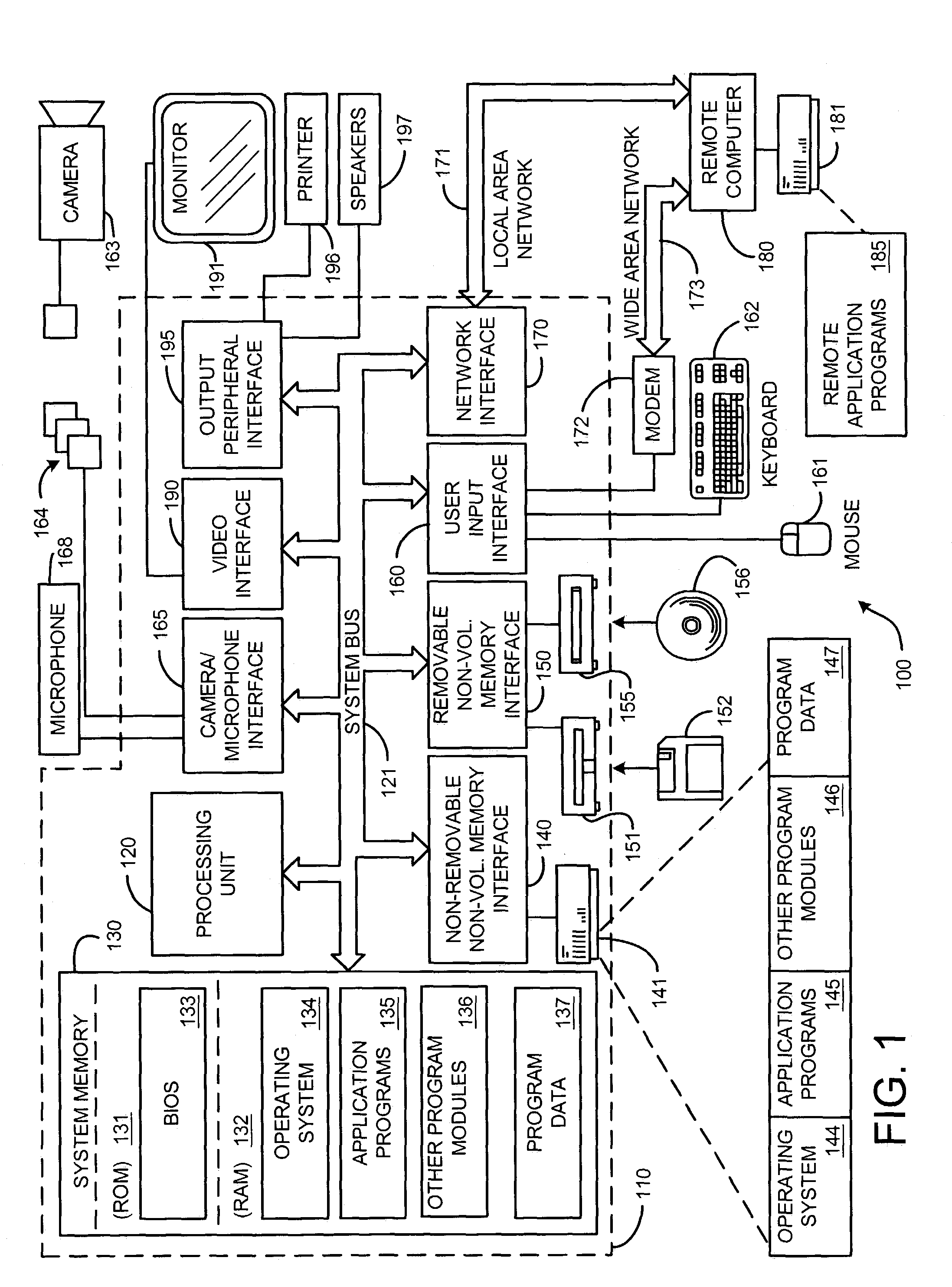
[0030]FIG. 1 illustrates an example of a suitable computing system environment 100 on Which the invention may be implemented. The computing system environment 100 is only one example of a suitable computing environment and is not intended to suggest any limitation as to the scope of use or functionality of the invention. Neither should the computing environment 100 be interpreted as having any dependency or requirement relating to any one or combination of components illustrated in the exemplary operating environment 100.

[0031]The invention is operational with numerous other general purpose or special purpose computing system environments or configurations. Examples of well known computing systems, environments, and / or configurations that may be suitable for use with the invention include, but are not limited to, personal computers, server computers, hand-held or laptop devices, multiprocessor systems, microprocessor-based systems, set top boxes, p...


PUM


Abstract

A whiteboard view camera, which in one embodiment is mounted on a boom, which is fixed above the whiteboard. However, the whiteboard view camera can also be wall or table mounted. The whiteboard view camera differs from an ordinary camera by allowing the lens to tilt with respect to the sensor plane, and shift with respect to the central ray. When the tilt angle α is zero, then the resolution of whiteboard is uniform (e.g., the top and bottom of the whiteboard have the same resolution). In addition, the focus plane is equal to the whiteboard plane, so depth of field issues are not a problem (e.g., a large aperture can be used). Hence, no image noise is introduced. A key contribution of the whiteboard view camera configuration according to the invention is the use of a view camera to capture whiteboard images at uniform resolutions. One embodiment of the whiteboard view camera employs a microphone array of the invention and uses a computer to optimize the image data and audio signals.

Description

BACKGROUND[0001]1. Technical Field[0002]This invention is directed toward a new whiteboard capture camera design. More specifically, this invention is directed toward a camera system and device for providing uniform resolution images of a whiteboard.[0003]2. Background Art[0004]Many meeting scenarios use a whiteboard extensively for brainstorming sessions, lectures, project planning meetings, patent disclosures, and so on. Note-taking and copying what is written on the board often interferes with many participants' active contribution and involvement during these meetings. As a result, some efforts have been undertaken to capture whiteboard content in some automated fashion.[0005]Several technologies have been developed to capture whiteboard content automatically. More recent technologies attempt to capture the whiteboard content in digital form from the start, especially in image form. National Television System Committee (NTSC)-resolution video cameras are often used because of th...

Claims


Application Information

Patent Timeline
IPC IPC(8): H04N5/262G06K9/36H04N5/225
CPCH04N1/19594H04N5/2251H04N5/2259H04N5/2254H04N2201/0438H04N23/58H04N23/661H04N23/695
Inventor CUTLER, ROSS
Owner MICROSOFT TECH LICENSING LLC
Why Eureka
Try Eureka