Dyeing apparatus and method therefor

a dyeing apparatus and fabric technology, applied in the direction of dyeing process, other washing machines, liquid cleaning, etc., can solve the problems of frequent deformation of the guide roller, the squeezing roller, the guide roller, etc., and the reference machine for continuous dyeing is prone to producing uneven dyeing results

Inactive Publication Date: 2008-07-15
ZZAKEY TECH
View PDF15 Cites 1 Cited by
  • Summary
  • Abstract
  • Description
  • Claims
  • Application Information

AI Technical Summary

Problems solved by technology

When the fabric for dyeing is a three-dimensional fabric, a narrow fabric having a plurality of hard protrusions, and the like, the above-referenced machines for continuous dyeing are prone to producing an unevenly dyed product, due to uneven pressure from the squeeze rollers.
Additionally, such machines may be subject to frequent deformation of the squeezing rollers, guides and feed rollers because the protrusions on the fabric continuously gouge these elements as the fabric traverses the machine.

Method used


Image

  • Dyeing apparatus and method therefor
  • Dyeing apparatus and method therefor
  • Dyeing apparatus and method therefor

Examples


first embodiment

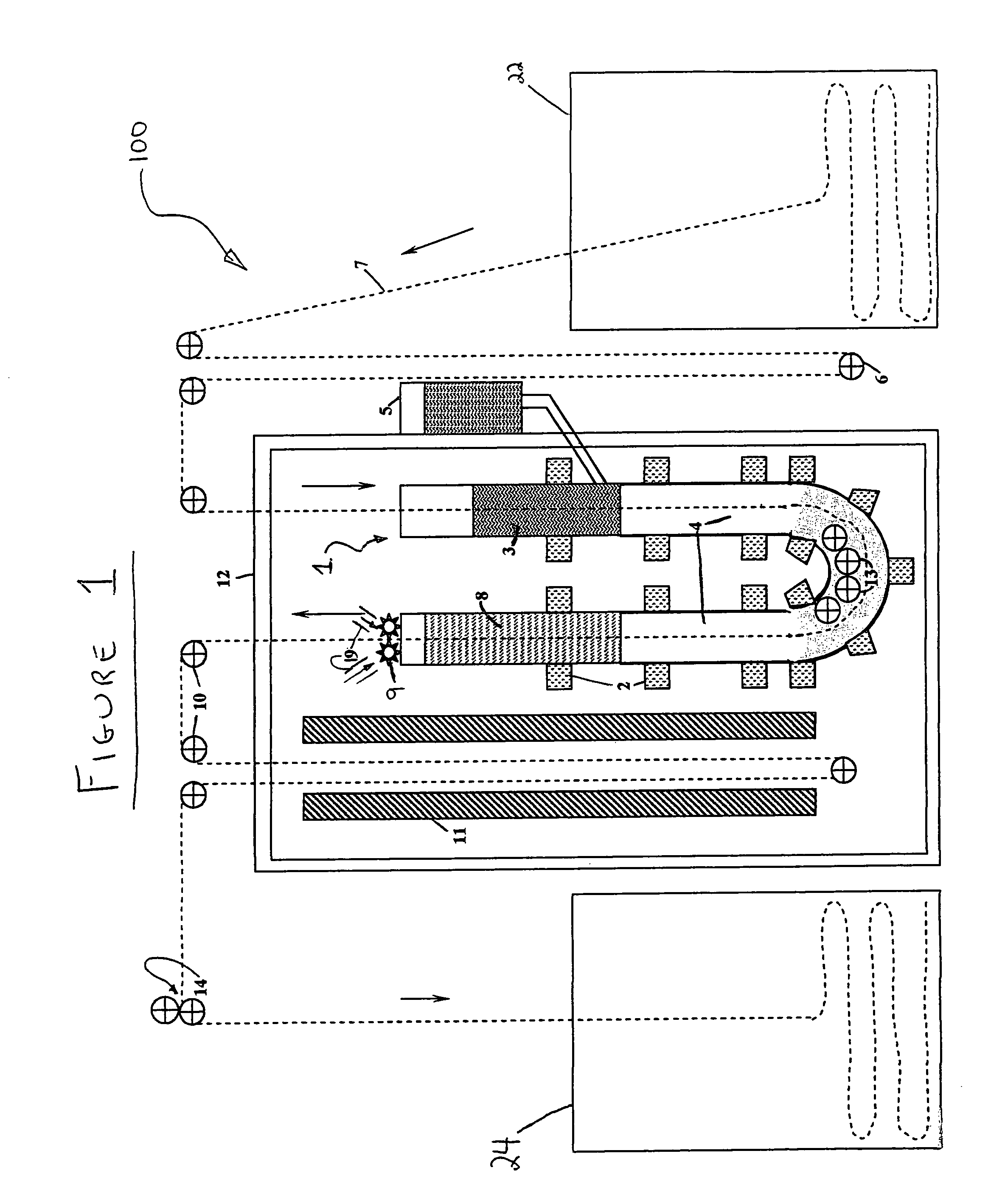
[0036]A schematic cross-sectional representation of a continuous dyeing apparatus 100 according to the present invention is provided in FIG. 1. Dyeing apparatus 100 preferably includes a dyeing vessel 1, electrical coil heating members 2, a dye reservoir 5, a let-off device 6, a tape or fabric 7 to be dyed, an air jet device 19 and / or a brushing device 9, guide rollers 10, a drying device 11, a frame 12, and a motorized transport device 14.

[0037]As will be elaborated hereinbelow, dyeing vessel 1 includes a dye liquor impregnation zone 3, a zone containing a high-density liquid heating medium 4, and a wash-off zone 8.

[0038]In the embodiment schematically provided in FIG. 1, dyeing vessel 1 is a vertically oriented, cylindrical “U”-shaped tube. Typically, dyeing vessel 1 has a height of 150 centimeters and a diameter of 10 centimeters, and contains a dense liquid for providing heat at 135° C. The liquid may contain bismuth, tin, lead, indium or cadmium, or a combination thereof (e.g.,...

second embodiment

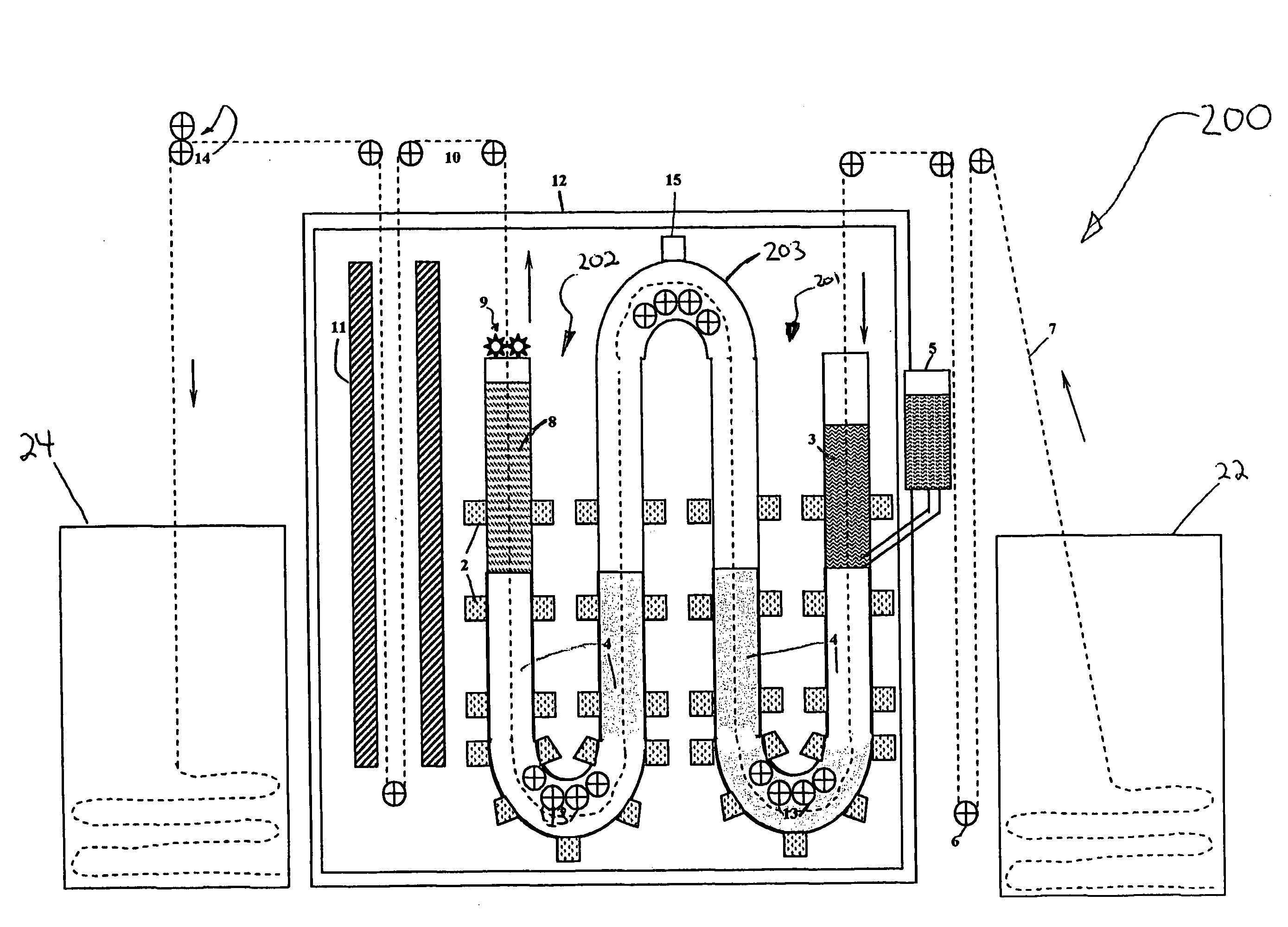
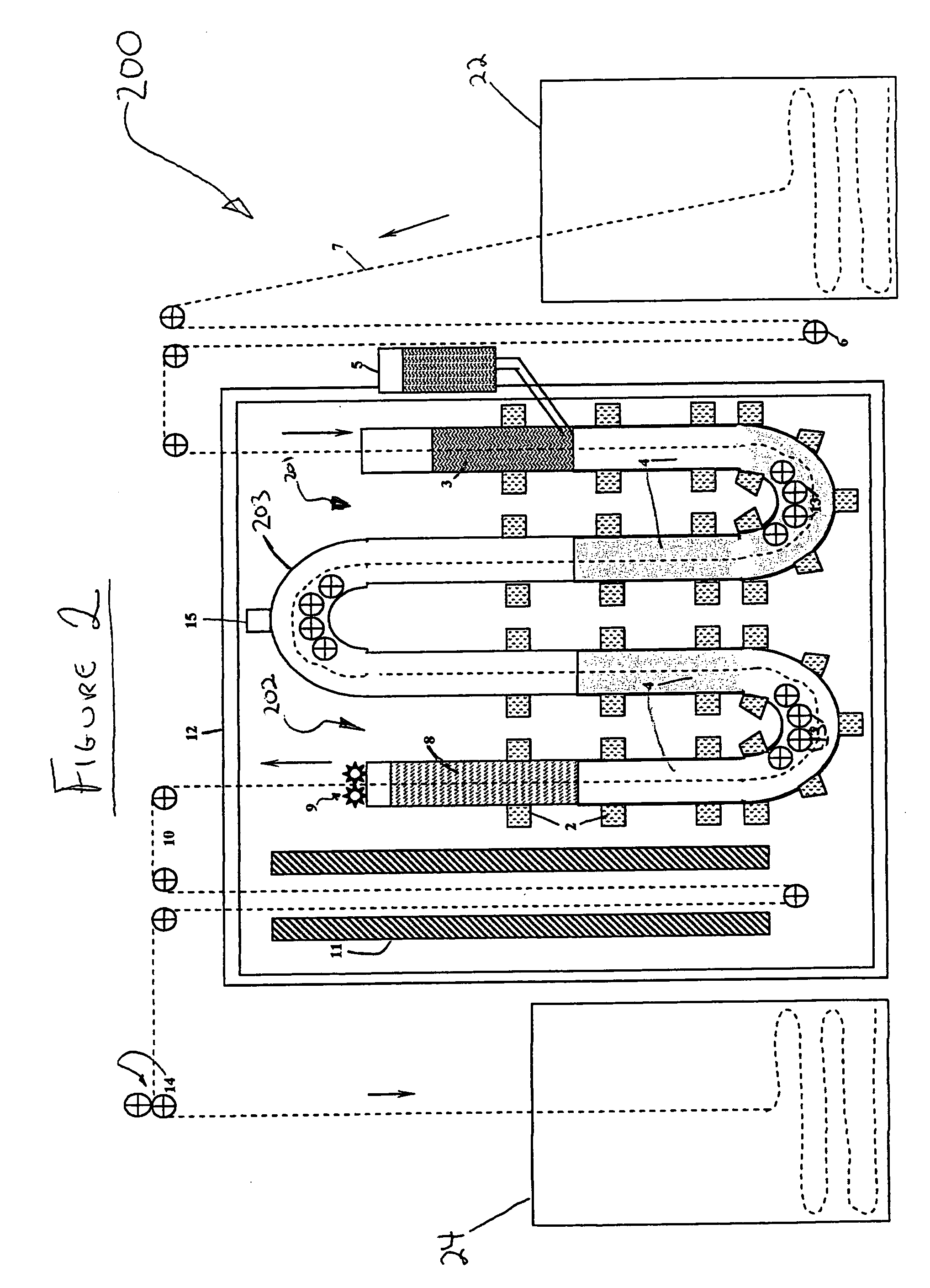
[0048]A schematic cross-sectional representation of a continuous dyeing apparatus 200 according to the present invention is provided in FIG. 2. Dyeing apparatus 200 is largely similar to dyeing apparatus 100 of FIG. 1, but the dyeing vessel includes two vertically oriented, cylindrical, U-shaped tubes 201, 202 and an inverted U-shaped cylindrical tube 203 connecting therebetween. Inverted U-tube 203 normally becomes at least partially filled with water vapor during the course of operation. Hence, inverted U-tube 203 is advantageously equipped with a controlled pressure release valve 15, for stabilizing the pressure within the system.

[0049]Fabric or tape 7 to be dyed is continuously fed from a package, box or reel 22 into the dyeing vessel, and is subsequently removed from the dyeing vessel, in a substantially identical method to that described with respect to FIG. 1.

[0050]By controlling the speed of traverse, the temperature and height of the liquid heating medium and the concentrat...


PUM

PropertyMeasurementUnit
temperatureaaaaaaaaaa
specific gravityaaaaaaaaaa

Abstract

A dyeing apparatus and method for continuous dyeing of a fabric article with dye, the apparatus including: (a) a dyeing vessel for containing a high-density liquid; (b) a heating mechanism, thermally associated with the dyeing vessel, for heating a dye fixation zone within the vessel to a temperature above 70° C.; (c) a continuous transport mechanism for continuously transporting the fabric article, through a dye impregnation chamber, and through the dye fixation zone of the dyeing vessel, and (d) a dye-dispensing mechanism for delivering a dye liquor within the dye impregnation chamber, so as to impregnate with the dye, the fabric article passing through the chamber, and wherein the dyeing vessel is dimensioned and configured such that a height of the high-density liquid delivers a hydrostatic pressure of at least 0.1 bar gauge to the dye fixation zone, so as to effect fixation of the dye in the fabric article.

Description

FIELD AND BACKGROUND OF THE INVENTION[0001]The present invention relates to a continuous fabric-dyeing apparatus and a method therefor, and, more particularly, to a continuous fabric-dyeing apparatus for, and method of, dyeing bulky, three-dimensional fabrics and narrow fabrics having a plurality of hard protrusions such as a trim tape, zip tape, hook-and-loop fastener tape, and braided cords.[0002]Various known machines for continuous dyeing of narrow fabrics rely on a dip trough and roller squeezing mechanism, commonly referred to as a padding machine, to control the amount of dye liquor deposited on the fabric (U.S. Pat. Nos. 5,050,258, 5,205,008, 4,878,365, and 3,995,457). The padding machine may include single or multiple baths (U.S. Pat. No. 4,997,453). Alternatives to squeeze rollers such as absorbent fiber webs, have been taught (U.S. Pat. No. 4,046,506). The impregnated fabric is then subjected to dry or steam heating to fix the dye in the fibers of the fabric (U.S. Pat. No...

Claims


Application Information

Patent Timeline
Patent Type & Authority Patents(United States)
IPC IPC(8): B08B3/12D06F31/00D06F33/00D06F37/00D06F5/00
CPCB08B1/02B08B3/041D06P7/00D06B19/0082B08B5/026
Inventor SHALEV, ITZHAKFAULKNER, KIRK E.
Owner ZZAKEY TECH
Why Eureka
Try Eureka