Transmitter patterns for multi beam reception

a multi-beam, transmitter technology, applied in tomography, instruments, applications, etc., can solve the problems of increasing sensor cost with the number of elements in the array and the number of processing channels, and the inability to monitor blood velocity in the intensive care unit or surgical application. , to achieve the effect of greater resolution

Inactive Publication Date: 2008-07-15
PHYSIOSONICS
View PDF73 Cites 114 Cited by
  • Summary
  • Abstract
  • Description
  • Claims
  • Application Information

AI Technical Summary

Benefits of technology

[0009]There is provided, in accordance with the present invention, a new, useful, and unobvious method of determining parameters of blood flow, such as vector velocity, blood flow volume, and Doppler spectral distribution, using sonic energy (ultrasound) and a novel thinned array. Also provided is a novel method of tracking blood flow and generating a three dimensional image of a blood vessel of interest that has much greater resolution than images produced using heretofore known ultrasound devices and methods.

Problems solved by technology

Blood velocity monitoring is not currently practical for intensive care unit (ICU) or surgical applications.
Slight movements cause the probe to lose the blood velocity signal.
However, in order for a two dimensional (2-D) device to provide such imaging normally requires thousands of elements, and must form many thousands of pencil beams every 1 / 30second.
Sensor cost grows with the number of elements in the array and the number of processing channels.
Thus, such devices are cost prohibitive, as well as impractical.
Moreover, no automated procedure exists in current practice for precisely locating the optimum point at which to measure the Doppler signal.

Method used


Image

  • Transmitter patterns for multi beam reception
  • Transmitter patterns for multi beam reception
  • Transmitter patterns for multi beam reception

Examples


example 1

An Ultrasound Diagnostic and Monitoring Sensor with Real-Time 3-D Mapping and Tracking of Blood Flow

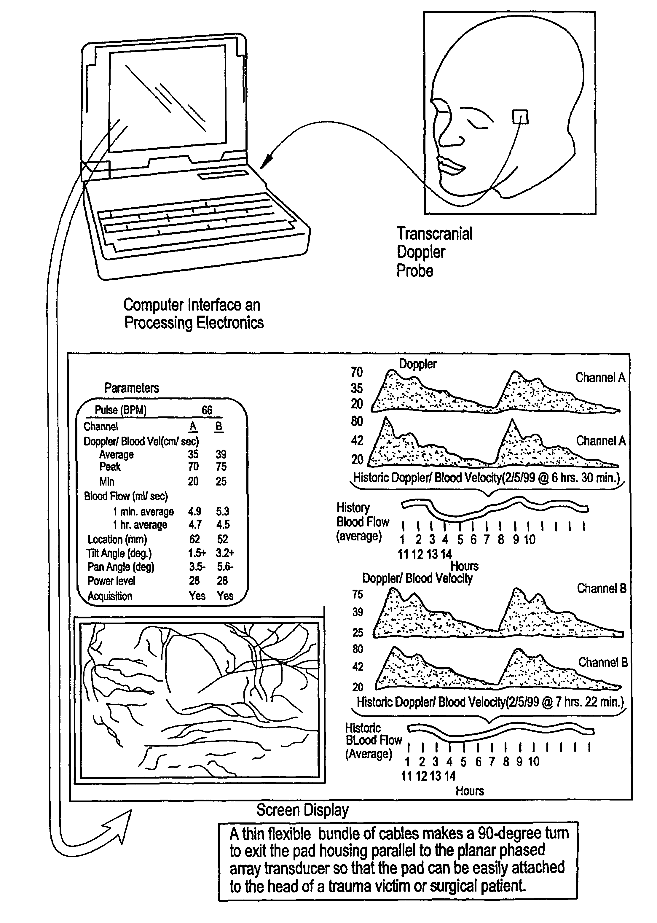
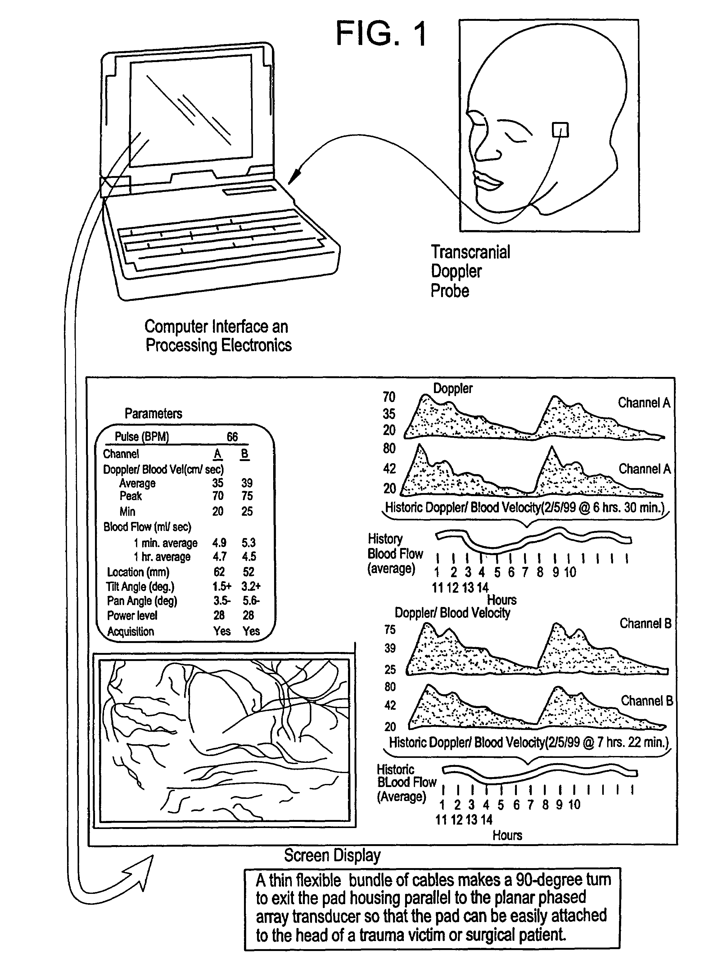
[0214]This embodiment of the present invention has application for medical evaluation and monitoring multiple locations in the body; however, the transcranial Doppler application will be used as an example to describe the invention.

[0215]This invention provides: (1) affordable three-dimensional imaging of blood flow using a low-profile easily-attached transducer pad, (2) real-time vector velocity, and (3) long-term unattended Doppler-ultrasound monitoring in spite of motion of the patient or pad. None of these three features are possible with current ultrasound equipment or technology.

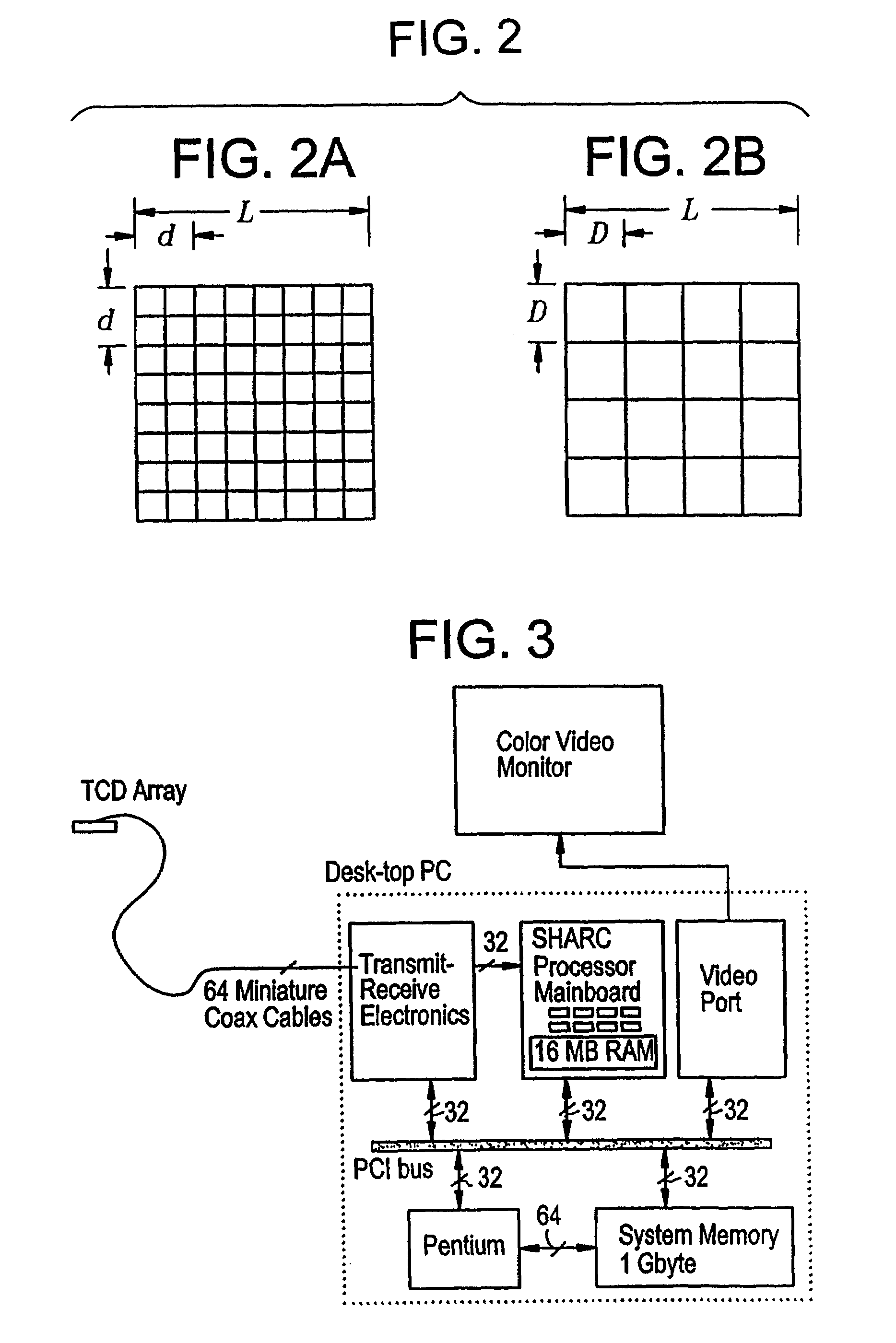
[0216]The pad and associated processor collects and Doppler processes ultrasound blood velocity data in a three dimensional region through the use of a planar phased array of piezoelectric elements. Through use of unique beamforming and tracking techniques, the invention locks onto and tracks the points ...

example ii

Ultrasound Measurement of Blood Volume Flow

[0298]As explained above, current ultrasound Doppler devices measure radial velocity. Several methods now exist for 3-D ultrasound imaging, such as those involving transducer motion. A three-dimensional image with Doppler allows for the measurement of vector velocity. Example I above provides measurement and long term monitoring of three-dimensional vector velocity. If the resolution of a color flow Doppler image is sufficient to provide an estimate of the inside diameter of the blood vessel, then measurement of volume blood flow becomes practical. Presently available ultrasound imaging devices have either low resolution or they only produce a two-dimensional image. The present invention combines vector velocity information (such as attained as explained in Example I above) with additional information to obtain volume flow. The additional information is the inside diameter of the vessel under examination, the blood velocity profile across t...

example iii

3-D Doppler Ultrasound Blood Flow Monitor with Enhanced Field and Sensitivity

[0330]This example sets forth an ultrasound Doppler device and method that enables non-invasive diagnosis (the conventional role of ultrasound systems), and also non-invasive unattended and continuous monitoring of vascular blood flow for medical applications. In particular, the embodiment of the present invention set forth in this example provides: (1) affordable three-dimensional imaging of blood flow using a low-profile easily-attached transducer pad, (2) real-time vector velocity, and (3) long-term unattended Doppler-ultrasound monitoring in spite of motion of the patient or pad. None of these three features are possible with current ultrasound equipment or technology.

[0331]The pad and associated processor collects and Doppler processes ultrasound blood velocity data in a three-dimensional region through the use of a two-dimensional phased array of piezoelectric elements on a planar, cylindrical, or sph...


PUM


Abstract

Provided herein is a method for use in medical applications that permits (1) affordable three-dimensional imaging of blood flow using a low-profile easily-attached transducer pad, (2) real-time blood-flow vector velocity, and (3) long-term unattended Doppler-ultrasound monitoring in spite of motion of the patient or pad. The pad and associated processor collects and Doppler processes ultrasound blood velocity data in a three dimensional region through the use of a planar phased array of piezoelectric elements. The invention locks onto and tracks the points in three-dimensional space that produce the locally maximum blood velocity signals. The integrated coordinates of points acquired by the accurate tracking process is used to form a three-dimensional map of blood vessels and provide a display that can be used to select multiple points of interest for expanded data collection and for long term continuous and unattended blood flow monitoring. The three dimensional map allows for the calculation of vector velocity from measured radial Doppler.
A thinned array (greater than half-wavelength element spacing of the transducer array) is used to make a device of the present invention inexpensive and allow the pad to have a low profile (fewer connecting cables for a given spatial resolution). The full aperture is used for transmit and receive so that there is no loss of sensitivity (signal-to-noise ratio) or dynamic range. Utilizing more elements (extending the physical array) without increasing the number of active elements increases the angular field of view. A further increase is obtained by utilizing a convex non-planar surface.

Description

CROSS REFERENCE TO RELATED APPLICATIONS[0001]This application is a continuation-in-part of U.S. application Ser. No. 10 / 327,265, entitled “Transmitter Patterns for Multi Beam Reception” and filed Dec. 20, 2002, which is a continuation-in-part of U.S. application Ser. No. 09 / 926,666, entitled “Device and Method for Mapping and Tracking Blood Flow and Determining Parameters of Blood Flow” and filed Mar. 20, 2002 (now U.S. Pat. No. 6,682,483), which is a national phase application of International Application No. PCT / US00 / 14691, filed May 26, 2000, which claims priority to U.S. provisional application Ser. No. 60 / 136,364, filed May 28, 1999; 60 / 138,793, filed Jun. 14, 1999; and 60 / 152,886, filed Sep. 8, 1999. The above-referenced U.S. application Ser. No. 10 / 327,265 claims priority to U.S. provisional application Ser. No. 60 / 343,061, entitled “Transmitter Patterns for Multi Beam Reception” and filed Dec. 20, 2001 (inventor Abend). The disclosure of each of the foregoing applications is...

Claims


Application Information

Patent Timeline
Patent Type & Authority Patents(United States)
IPC IPC(8): A61B8/00A61B8/06G01S7/52G01S7/521G01S15/52G01S15/89
CPCA61B8/06G01S15/8993A61B8/463A61B8/483G01S7/52026G01S7/52034G01S7/5206G01S7/52061G01S7/52065G01S7/52071G01S7/52073G01S7/52074G01S7/52095G01S15/8927G01S15/8979A61B8/13G01S7/52079G01S15/52G01S15/899
Inventor ABEND, KENNETHATTIA, ELSAYED H.
Owner PHYSIOSONICS
Why Eureka
Try Eureka